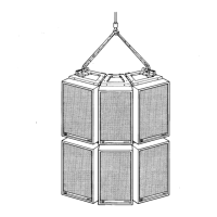
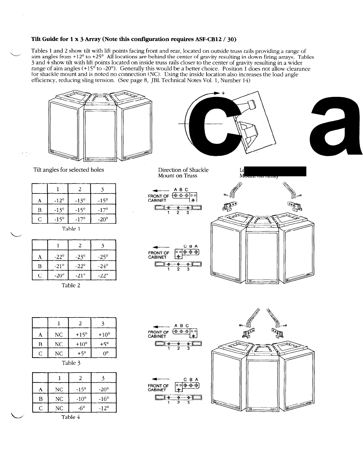
Tilt Guide for 1 x
3
Array (Note this configuration requires ASF-CB12 /
30)
L
Tables 1 and 2 show tilt with lift points facing front and rear, located on outside truss rails providing a range of
aim angles from +12’ to
+25’
All locations are behind the center of gravity resulting in down firing arrays. Tables
3 and 4 show tilt with lift points located on inside truss rails closer to the center of gravity resulting in a wider
range of aim angles (+15” to -20’). Generally this would be a better choice. Position
1
does not allow clearance
for shackle mount and is noted no connection (NC). Using the inside location also increases the load angle
efficiency, reducing sling tension. (See page 8, JBL Technical Notes Vol. 1, Number
14)
+
.
Tilt angles for selected holes
Table 1
Table 2
A
1
NC
+lj”
+lo”
I
I
I
1
B
1 NC 1
+lO’
1
+5’
I
1
C
1
NC
1
+5”
1
0'
]
Table
3
NC
1
-15”
1
-20’
Direction of Shackle
Location of Shackle
Mount on Truss
Mount on Array
[01~10]
1 2 3
I’l~TnJ
1 2 3
Table 4