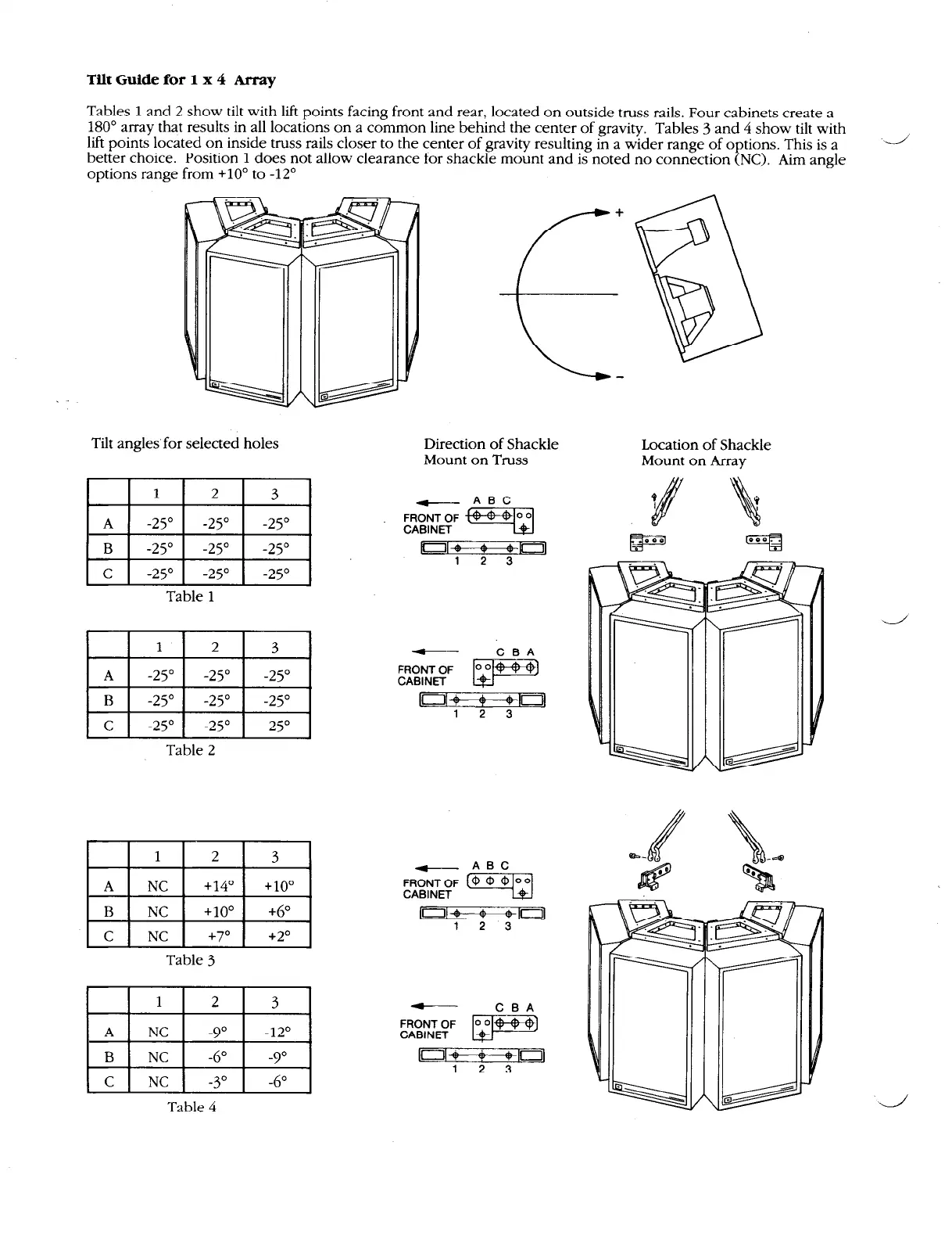
Tilt Guide for 1 x 4 Array
Tables
1
and 2 show tilt with lift points facing front and rear, located on outside truss rails. Four cabinets create a
180” array that results in all locations on a common line behind the center of gravity. Tables
3
and
4
show tilt with
lift points located on inside truss rails closer to the center of gravity resulting in a wider range of options. This is a
better choice. Position
1
does not allow clearance for shackle mount and is noted no connection (NC). Aim angle
options range from +lO” to -12”
Tilt angles for selected holes
Direction of Shackle
Location of Shackle
Mount on Truss
Mount on Array
1 2
3
-
ABC
A -25’
-25” -25”
y&gF i+GEp-J
B -25”
-25”
-25”
=?=R=
C -25”
-25”
-25’
Table 1
Table 2
1
2
3
A
NC
+14”
+10”
B
NC
+lo”
+6”
C NC
+7”
+2O
Table
3
pG$J
Table 4
-
CBA
FRONT OF
CABINET
p
I~M-+-+!a
1 2 3
[Old $ +cni
1 2 3