Do you have a question about the JBL K2 S9900 and is the answer not in the manual?
Electrical resistance of the loudspeaker system at different frequencies.
The highest power level recommended for amplifier connection.
The spectrum of audio frequencies the speaker can reproduce.
Loudness produced by the speaker for a given input power.
Frequencies where the signal is split between speaker drivers.
The main enclosure structure housing the speaker components.
Protective mesh covering for the loudspeaker drivers.
The driver responsible for reproducing bass frequencies.
The driver responsible for reproducing treble frequencies.
The driver for reproducing very high frequencies.
Test parameters for evaluating speaker performance across frequency bands.
Overall height, width, and depth of the loudspeaker unit.
Net and shipping weight of the loudspeaker system.
Diagram illustrating the internal electrical connections of the loudspeaker.
Circuit diagram detailing the low-frequency crossover network.
Circuit diagram detailing the high-frequency crossover network.
Circuit diagram detailing the ultrahigh-frequency crossover network.
Procedure for accessing internal batteries via the terminal cup.
Steps for safely removing the UHF driver assembly.
Detailed steps for extracting the woofer from the enclosure.
Instructions for removing the high-frequency horn and driver.
Guidance on locating and disconnecting the three crossover networks.
Visual representation of speaker components with part number references.
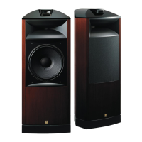
| Type | 3-way floorstanding speaker |
|---|---|
| Nominal Impedance | 6 Ohms |
| Sensitivity | 93dB (2.83V @ 1m) |
| Woofer | 15" (380mm) |
| Midrange | 4" (100mm) |
| Tweeter | 1" (25mm) |