Do you have a question about the JBL Soundgear Series and is the answer not in the manual?
Guidelines for handling and storing the pick-up unit safely.
Important considerations and warnings when repairing the pick-up mechanism.
Essential steps and precautions before starting CD player repairs.
Essential guidelines for handling components and tools during repairs.
Procedure for resetting the unit to its initial status via a reset wire.
Detailed specifications for the amplifier section of the units.
Technical details for the FM, AM, SW, and LW tuner sections.
Performance details for the cassette playback and recording functions.
Technical specifications for the CD playback functionality.
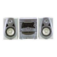
Overall specifications including power, dimensions, and weight.
Instructions for adjusting tape deck azimuth and speed settings.
Procedure for adjusting tape deck azimuth for optimal playback.
Steps for adjusting tape deck normal and hi-speed playback.
Procedure for setting record bias for tape recording.
Procedures for tuning the radio receiver for optimal signal reception.
Waveform characteristics of the HF or RF signal during normal play.
Waveform of the EFM signal at IC 801 during normal playback.
Waveforms related to focus coil drive during search or successful focus.
Waveforms for tracking coil drive during forward and backward traverse.
Waveform for the feed motor drive during normal play.
Wiring diagram illustrating connections for the SG2020 model.
Wiring diagram illustrating connections for the SG3030 model.
Block diagram showing the functional components of the SG2020.
Block diagram showing the functional components of the SG3030.
Schematic showing the power supply circuit for SG2020, version 1.
Schematic showing the power supply circuit for SG3030, version 2.
Schematic showing the power supply circuit for SG2020 UL version, 3.
Schematic showing the power supply circuit for SG3030 UL version, 4.
Schematic of the tuner section for SG2020, version 1.
Schematic of the tuner section for SG3030, version 2.
Schematic of the tuner section for SG2020 UL version, 3.
Schematic of the tuner section for SG3030 UL version, 4.
Schematic of the main board for SG2020, version 1.
Schematic of the main board for SG3030, version 2.
Schematic of the main board for SG2020 UL version, 3.
Schematic of the main board for SG3030 UL version, 4.
Schematic of the front panel for SG2020/SG3030, version 1.
Schematic of the front panel for SG2020/SG3030 UL version, 2.
Schematic of the deck mechanism for SG2020/SG3030, version 1.
Schematic of the deck mechanism for SG2020/SG3030 UL version, 2.
Component placement diagram for the SG2020 main board 1.
Component placement diagram for the SG3030 main board 2.
Component placement diagram for the SG2020 power board 1.
Component placement diagram for the SG3030 power board 2.
Component placement diagram for the front control board.
Component placement diagram for the tape deck mechanism board.
List of packaged items included with the SG2020 unit.
List of mechanical components and their part numbers for SG2020.
List of electrical components and their part numbers for SG2020.
List of packaged items included with the SG3030 unit.
List of mechanical components and their part numbers for SG3030.
List of electrical components and their part numbers for SG3030.
Diagram showing the assembly of the SG2020 cabinet components.
Diagram showing the assembly of the SG3030 cabinet components.
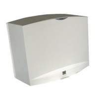
Diagram illustrating the assembly of the SG2020 speaker unit.
Diagram illustrating the assembly of the SG3030 speaker unit.
Diagram showing the assembly of the tape deck mechanism.
Diagram showing the assembly of the CD deck mechanism.
| Bluetooth | Yes |
|---|---|
| Wireless | Yes |
| Charging Time | 2 hours |
| Type | Wearable Speaker |
| Wearing Style | Neckband |
| Battery Life | 6 hours |
| Dimensions | 242 x 207 x 44 mm |