SMS1-SUB
This section gives detail of the parts of the Subwoofer Module.
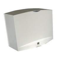
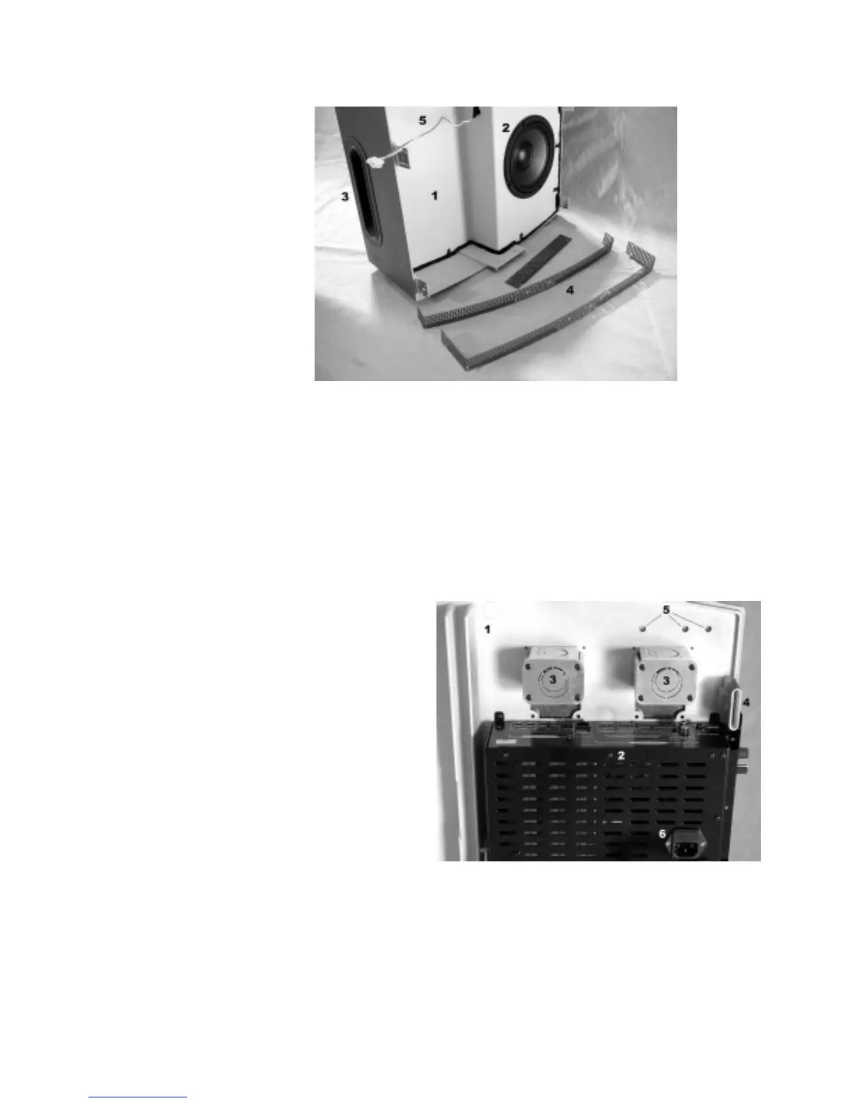
Figure 2 – Subwoofer Cabinet
1 - Cabinet Chassis – This is the main body of the low frequency cabinet.
2 - Driver – Low frequency Element
3 - Port Tube – This is one of the primary sound radiation locations.
4 - Grille Trim – These pieces go on after installation to trim and protect the module.
5 - Subwoofer Leads -These connect to the Electronic Module Subwoofer output.
6 - Rubber Screw Cover Pieces (not shown) - These pieces are used to cover the mounting screws when
the Subwoofer is assembled.
Wall Baffle and Electronic Module
Figure 3 –Wall Baffle and Module
1 - Wall Baffle – This baffle is the primary
mounting point. It is also the physical
mount for the Electronic Module
2 - Electronic Module – This is the housing for
all of the electronics, the connections
and the controls.
More detail is shown in Figure 4.
3 - Knockouts – These prepunched Knockouts
provide a location at which to connect
input and output conduit. There are two diameters accounted for 1/2” and 3/4”.
4 - Mounting Tabs – These tabs are for lining up and attaching the Subwoofer Cabinet to the Wall Baffle.
5 - Installation Points – These holes are molded in position to match with several standard dimensions for
wall stud placement. They accommodate 5/32 in. (4mm) Bolts.
6 - Power Cord Input Jack
– This Jack is for the IEC Power Input Cord to supply power to the SMS1
System.
4
 Loading...