03 - Attachments, Couplings and Load Handling
09 - Lift Arm Quickhitch
06 - Hydraulic Quickhitch
03 - 9 9813/4800-3 03 - 9
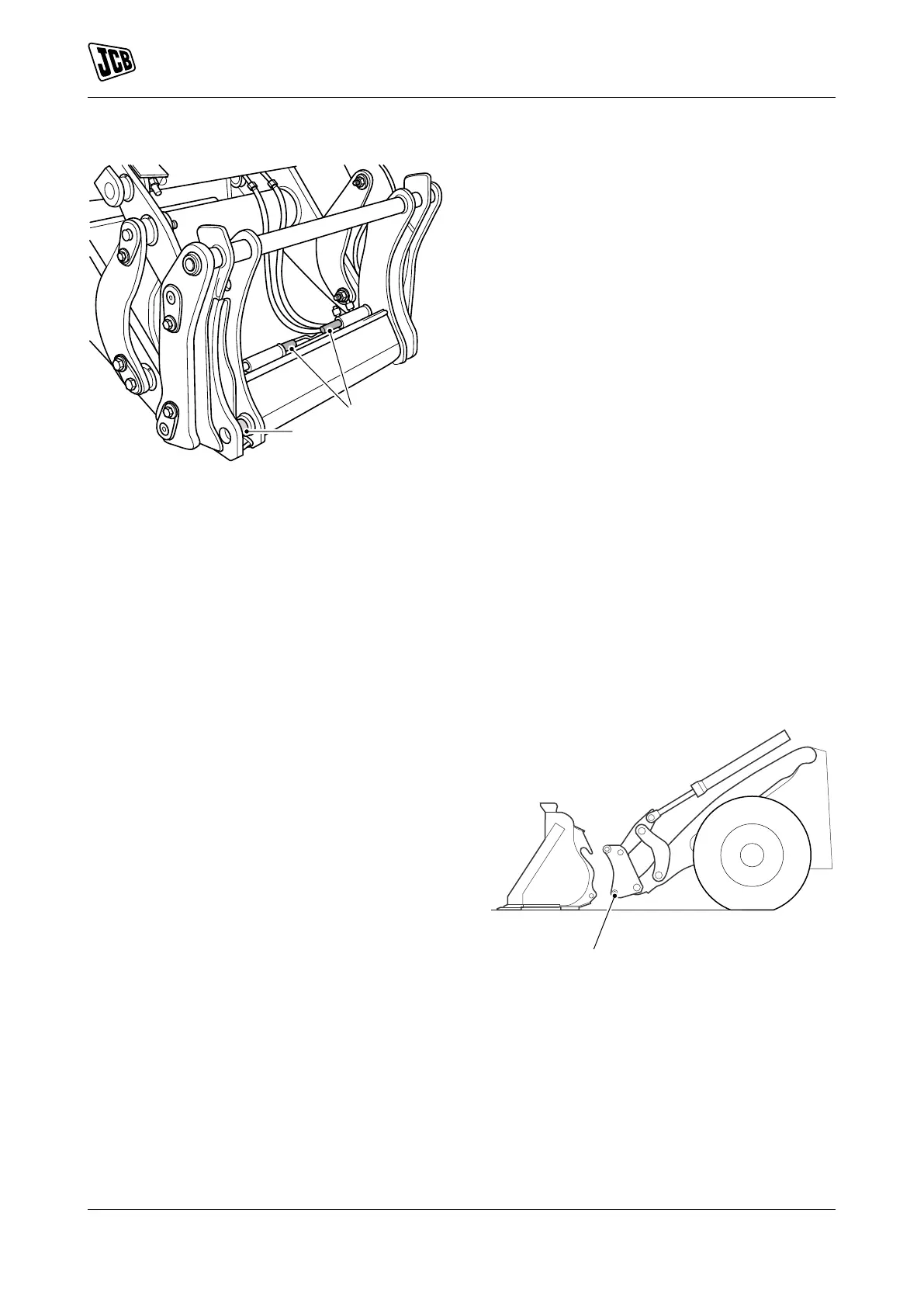
Figure 13.
A Locking pins
B Indicators
Lubricate
Remove the attachments before you grease the
locking pins. Total of 2 grease points. Refer to Figure
13.
When working in difficult conditions, grease and
operate the locking-pins every 10 hours.
Disconnect and Connect
Disconnect
1. Park the machine on hard, level ground, then
lower the attachment. Refer to (PIL 01-03).
2. Apply the park brake and put the transmission
into Neutral. If necessary, disconnect the
hydraulic hoses.
3. If installed, push and hold the quickhitch isolator
switch.
4. Disengage the locking pins.
4.1. Operate the auxiliary lever roller switch on
the operating lever to disengage the locking
pins.
5. Release the quickhitch isolator switch.
6. Disengage the attachment.
6.1. Operate the auxiliary lever roller switch on
the operating lever to disengage the locking
pins.
7. When the pivot-shaft has disengaged from the
hooks, reverse the machine away from the
attachment.
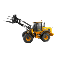
Figure 14.
A Locking pins