P/N 960-100929R_Rev. 7 {EDP #148849} © 2017, JAPAN CASH MACHINE CO., LTD.
Page
iVIZION® Series Next-Generation Banknote Acceptor Unit
Table of Contents
Tool Requirements ........................................................................................................ 4-1
Pusher Unit Timing Belt Removal ................................................................................ 4-1
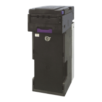
iVIZION Standard and Large Cash Box ........................................................................... 4-1
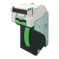
iVIZION HC Cash Box ..................................................................................................... 4-3
Home Position Sensor Board/Home Position Sensor, FFC & Interface Connector
Board Removals ............................................................................................................ 4-5
RFID Module & Harness Removals .............................................................................. 4-6
Validation CPU & Controller CPU Board Removals ................................................... 4-6
USB FPC, Power FPC & Interface FPC Cable Removals ........................................... 4-7
Validation Unit Harness Removal ................................................................................ 4-8
Interrupter Board Removal ........................................................................................... 4-8
Motor Unit Timing Belt Removal ...................................................................................... 4-8
Stacker Motor & Transport Motor Removals ............................................................... 4-9
Bezel Hold Clips A & B Removal .................................................................................. 4-9
Sensor Transfer Board/CIS FFC/Transmissive Light FFC & Upper UV FPC Sensor
Removals ........................................................................................................................ 4-9
Validation Sensor Board Assembly Removal ........................................................... 4-10
Validation Sensor FPC Cable Removal ..................................................................... 4-10
CIS/Transmissive Light & Upper UV Sensor Removals ........................................... 4-11
CIS/CIS FPC/Lower UV Sensor & Lower UV FFC Removal ..................................... 4-12
Validation Unit Timing Belt Removal ......................................................................... 4-14
Reassembly Cautions ................................................................................................. 4-14
5 WIRING DIAGRAMS .............................................................................................. 5-1
iVIZION System Wiring Diagram .................................................................................. 5-1
6 CALIBRATION AND TESTING ..............................................................................6-1
Tool Requirements ........................................................................................................ 6-1
Installation Procedures ................................................................................................. 6-1
Application Software Installation ...................................................................................... 6-1
Driver Installation Procedure ........................................................................................... 6-2
JCM Tool Suite Standard Edition Mode ....................................................................... 6-3
Download Procedures ................................................................................................... 6-3
Download the Upgrade Program .................................................................................................6-3
Downloading the Program First Time ..........................................................................................6-4
Calibration ...................................................................................................................... 6-6
When to Calibrate ........................................................................................................................6-6
Calibration Order ......................................................................................................................6-6
Calibration Tool Requirements ....................................................................................................6-6
Reference Paper Placement ........................................................................................... 6-6
Placing the KS-072/KS-089 Reference Paper ............................................................................6-6
Calibration Procedure .................................................................................................................. 6-7
Calibration Only ........................................................................................................................6-7
Calibration Plus Serial Number Writing ................................................................................... 6-10
Performance Tests ....................................................................................................... 6-11
Performance Test Items using a PC .............................................................................. 6-11
 Loading...