Do you have a question about the Jedia JSC-132A and is the answer not in the manual?
Risk of electric shock, do not open.
Read before operating, installation conditions, and precautions.
Detects ground faults in speaker lines.
Checks speaker line impedance.
Checks for open speaker lines.
Checks for speaker line overload.
Checks for speaker line underload.
Checks for speaker line short circuits.
Supports up to 32 speaker lines with 4 relay boards.
Automatic checking at adjustable intervals from 1 min to 24 hrs.
Double-spaced background-lighted LCD with clear text.
Interrupts check on emergency announcement.
Bridges volume control with integrated relay during check.
Supports 100V/70V speaker line checks.
Stores data using non-volatile memory.
Alerts with sound and LED for speaker line faults.
Allows disabling the buzzer sound.
Operates on AC and DC 24V.
Standard 19" rack mount or desktop installation.
Unit installation and connection of relay boards.
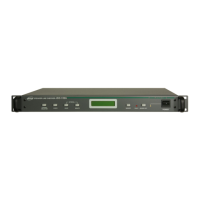
Selects the channel to check (1-32).
Initiates the line status check for the selected channel.
Sets the automatic checking interval from 1 min to 24 hours.
Displays equipment information (16 characters, 2 lines).
Stores checked channel and adjusted time intervals.
LED indicates fault status (open, short, impedance, ground).
Stops the buzzer sound when a fault is detected.
Controls AC power input.
Connects the AC power cord.
Holds the AC fuse for power protection.
For DC 24V battery power supply during AC failure.
Input terminal to temporarily disable measurement.
Normally-open relay contact activated on fault detection.
Normally-open relay contact active during measurement.
Connectors for up to 4 relay boards.
Switches to enable or disable checking for individual channels.
Input terminals for amplifier signals for each channel.
Output terminals for amplifier signals and measurement signals.
Connectors to link the JSC-132D with the JSC-132A.
Expands JSC-132A, 16-channel support, rack-mountable.
Check range, time, input/output, ADC resolution.
Power consumption, source, dimensions, weight.
Displays initial status and auto-check time on LCD.
Shows fault status and channel details if previous faults exist.
Displays memorized channel status after check or stop.
Shows "input CHECK STOP" status on the rear panel.
Select channel, check status, and memorize settings.
Indicates if a relay board is not connected for a channel.
Shows "Switch Off" if a channel's switch is off.
Initiates check and displays results compared to memory.
Detailed display of fault types and buzzer/LED activation.
Memorizes new standard values with "Writing Ok!" or "Back-Up Error!".
Performs a final check after saving new standard values.
Sets automatic checking intervals from 1 minute to 24 hours.
Memorizes new time interval settings with "Writing Ok!" or "Back-Up Error!".
Performs a check on all connected channels simultaneously.
Stops the buzzer sound when a fault is detected.
Guides through the initialization and calibration process.
Clears stored memory data and resets settings.
Recommended wiring diagram for 2-wire connection.