Do you have a question about the Jegs 90098 and is the answer not in the manual?
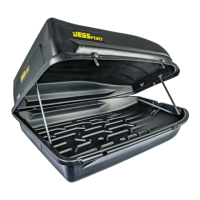
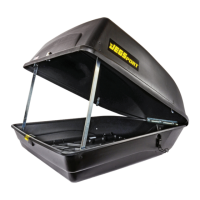
The main cargo box component, with a capacity of 18 cubic feet.
A warning sticker to be placed for user safety and to remind of potential hazards.
Eight threaded knobs used for securing the cargo carrier to the vehicle's cross rails.
Four metal plates that provide a base for attaching the mounting brackets to the carrier.
Four brackets that connect the carrier's mounting plates to the vehicle's cross rails.
Two keys provided for locking the cargo carrier securely.
Ensure all parts are received before proceeding with installation; contact support if any are missing or damaged.
The carrier can be installed without tools; professional assistance is an option if uncomfortable.
Installation necessitates a vehicle roof rack and cross rails, which are not included with this kit.
Trial fit all components before modification; used or modified carriers are not eligible for return.
Read all instructions carefully; warranty covers defects, excluding damage to vehicles, contents, or persons.
Use discretion for attachment; consult owner's manual for rack capacity, not exceeding 110 lbs.
Ensure hardware is tight and locked; periodically inspect for security; carrier is moisture-resistant.
Remove carrier when not in use or before low clearance areas; secure locks before driving.
Avoid high speeds with empty carriers; ensure the carrier is properly secured and attached.
Install the 'Low Clearance' decal on the rearview mirror to prevent accidents.
Place and align the top shell on the bottom, ensuring all four lock cams are in the unlocked position.
Confirm lock cams are correctly seated in the bottom shell slots for proper locking mechanism function.
Lock one side of the carrier, then position and lock the opposite side to secure the top to the bottom shell.
Set cross rails to 24 inches spacing and attach the carrier, drilling new holes if necessary for vehicle fit.
Align the bottom box mounting holes with each side of the vehicle's cross rails for secure attachment.
Raise the uprights on each end into the locked position, using the closest upright and bracket for stability.
Place mounting brackets through cross rail holes and slide mounting plates over threaded posts inside the carrier.
Distribute cargo weight evenly, do not exceed load limits, and secure the bale latch into its locked position.
Close the top lid and ensure all four cam locks are engaged in their slots; remove keys for security.
Verify bale latch is secured and lid cannot be lifted; all locks must be engaged with keys removed when vehicle is in motion.
| Brand | Jegs |
|---|---|
| Model | 90098 |
| Category | Automobile Accessories |
| Language | English |