- - 10 - -
Jet Inc. 750 Alpha Drive Cleveland, OH 44143 www.jetincorp.com 800.321.6960
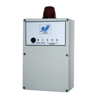
Auto-dialer interface
The circuit board has a
connector configured to
provide power and a
triggering signal to select
models of commercial,
automatic telephone voice
dialers. If an Auto-Dialer is
installed on the model 197
Control Panel use wire ties
to secure RJ-10 cable to
LED array mounting posts to
ensure there is no contact
between the RJ-10 cable
and 197 control panel
printed circuit board or
components (see image at
right)
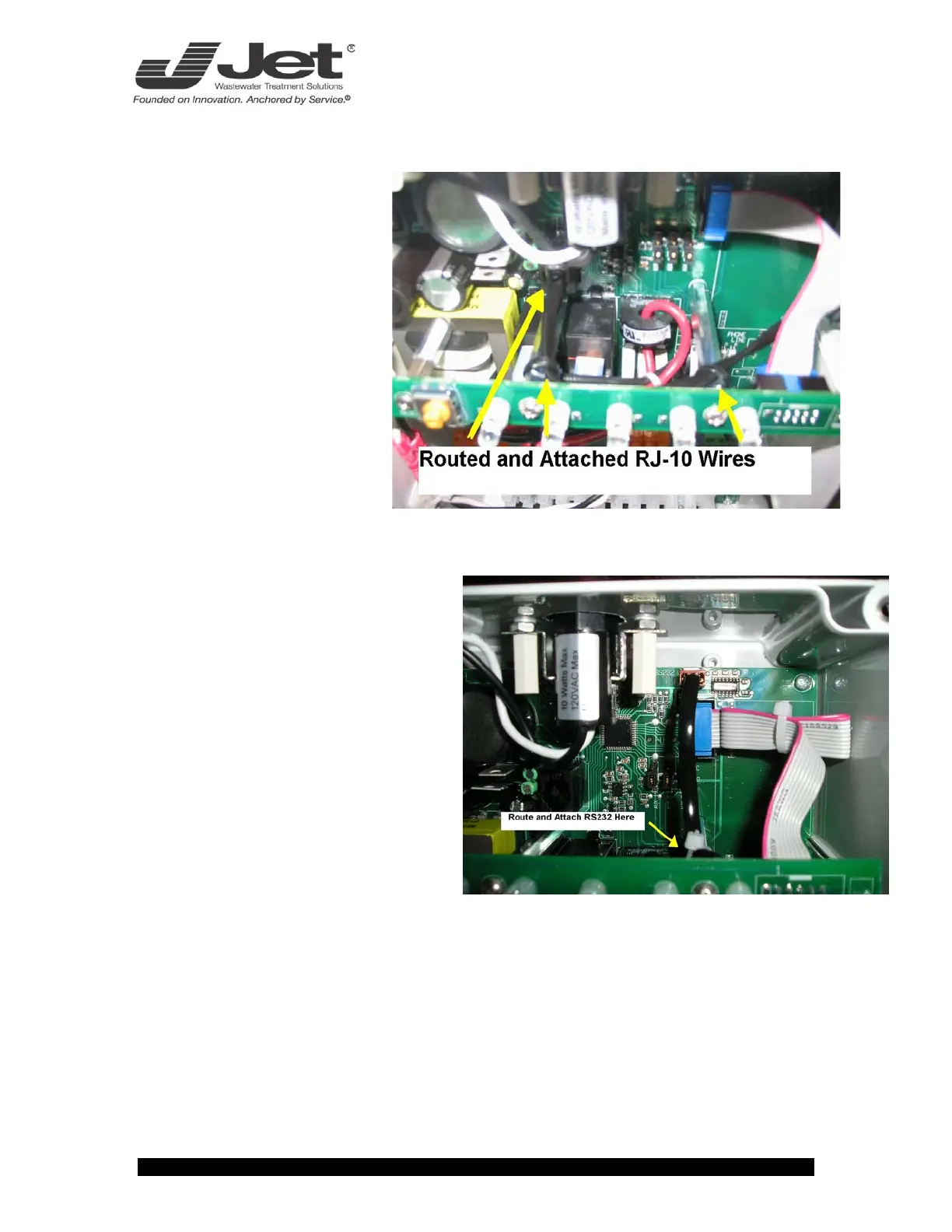
RS232 interface circuit
An interface circuit for RS232
communications allows for
connection of the panel to a
computer or other data logging
equipment. If this equipment is
connected to the model 197 Control
Panel use wire ties to secure RS232
cable to LED array mounting posts to
ensure there is no contact
between the RS232 cable and 197
control panel printed circuit board
or components (see image at
below).
Fuse and power switch
The power to the on-board circuitry and to the auxiliary outputs is fused and there
is an on-board power switch for use by service or maintenance personnel.