EasyManua.ls Logo

Jet 197 User Manual

Jet 197
14 pages
To Next Page IconTo Next Page
Page #1 background imageLoading...
Page #1 background image
- - 1 - -
Jet Inc. 750 Alpha Drive Cleveland, OH 44143 www.jetincorp.com 800.321.6960
QA-SAL-132 REV 7/31/2013
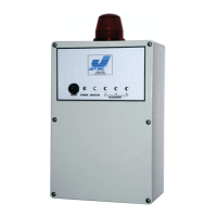
Jet Inc. Model 197 Control Panel
Installation and Users Manual
The Jet Incorporated Aerator control panel monitors and controls the operation of
Jet system aerators and additional components. The panel can be configured to
control single or dual aeration systems. A single aerator system controls the
operation of one aerator. A dual aerator system can control two aerators, or one
aerator and one re-aeration compressor.
In addition to the aerator control circuits, the control panel also contains the
following circuits or features:
Two aerator/compressor control circuits
Three auxiliary output circuits
Three auxiliary input circuits with normally open or normally closed
selection
One power indicator LED, and four additional error indicator LED’s
An alarm buzzer with circuit board provision for an alternate or externally
mounted buzzer
A 9-position DIP switch for selection of configuration options
User accessible reset switch and circuit board master reset switch
Alarm mode Auto-Dialer power and control interface
RS232 interface circuit
Circuit board mounted power switch and fuse
Control Panel Features
A. Master Reset Button
B. Internal Horn
C. On/Off Switch
D. External Reset Button
E. Pump Power Supply Contacts
F. Alarm and Aerator Power Supply Contacts
G. Ground Buss
H. Central Alarm Beacon
I. DIP Switch Array
J. Auxiliary Alarm Settings (NC/NO)
K. Indicator Light Array
L. Auxiliary Alarm Contacts
M. Auxiliary Alarm Contacts

Questions and Answers:

Jet 197 Specifications

General IconGeneral
BrandJet
Model197
CategoryControl Panel
LanguageEnglish

Summary

Safety Instructions and Precautions

Hazardous Voltage Warning

Highlights severe risks like shock, burns, or death from hazardous voltage.

Manual Usage Instructions

Emphasizes thorough review of instructions and warnings before performing work.

General Safety Precautions and Wiring Standards

Covers grounding, lockout, voltage matching, thermal protectors, and qualified technicians.

Wiring and Installation Procedures

Jobsite Wiring Guidelines

Details requirements for conduit, cable measurement, burial depth, and connections.

Control Panel Mounting and Location

Specifies panel placement for accessibility, visibility, and protection from elements.

Sample Hub and Connector Installation

Carflex Fittings Installation

Provides step-by-step instructions for installing Carflex conduit fittings.

Control Panel Settings and Functions

Aerator Timer Control Settings

Explains DIP switch configurations for aerator run times and continuous operation.

Auxiliary Output Control Configuration

Details DIP switch settings for auxiliary alarm functions and output activation.

Multiple Aerator Control Options

Describes DIP switch settings for aeration alarm sensing and current sensing.

Test Mode Control Setting

Explains the function of the DIP switch for enabling test mode.

System Operation Details

Aerator and Compressor Monitoring

Covers monitoring, control, duty cycles, and automated reset for aerator/compressor circuits.

Pump Motor Control Operation

Describes the pump motor control circuit and its behavior during alarm conditions.

Auxiliary Output Control Function

Explains the function of auxiliary output circuits and their control of 120VAC.

System Components and Features

Auxiliary Input Functionality

Details the purpose and operation of auxiliary inputs for sensing system components.

Indicator LED Functions

Describes the function of the power indicator and error indicator LEDs.

Alarm Buzzer Operation

Explains when the alarm buzzer sounds and its silencing options.

Reset and Master Reset Switches

Describes the dual functionality of the user-accessible reset and the master reset switch.

Interface and Power Management

Auto-Dialer Interface Connection

Explains the connector for providing power and triggering signals to auto-dialers.

RS232 Interface Circuit

Details the interface for RS232 communications for panel to computer connection.

Fuse and Power Switch

Describes the fused power for onboard circuitry and the power switch for service.

Start Up Check List

Pre-Operation System Checks

Lists essential checks for system configuration, wiring, and component readiness.

Initial Power On and Testing

Guides on turning on power, performing self-tests, and verifying voltage levels.

Final Checks and Warranty Card

Details returning test mode, resetting the panel, and completing warranty information.

Troubleshooting Guide

Power and Alarm Troubleshooting

Addresses issues like no power to panel, aerator/auxiliary alarms after startup.

Aerator and Pump Troubleshooting

Covers problems such as no power to aerators/pump, and timer/reset malfunctions.

Auxiliary and Compressor Troubleshooting

Details troubleshooting for inactive auxiliary outputs and compressor alarms.

Electrical Wiring Diagram

Model 197 Control Panel Wiring

Provides a diagram for connecting aerators, compressors, pumps, and auxiliary equipment.

1-Year Limited Warranty

Warranty Coverage and Claim Process

Outlines warranty period, coverage for defects, and steps for making a claim.

Warranty Exclusions and Limitations

Details items not covered, damages excluded, and legal rights provided by the warranty.