- - 11 - -
Jet Inc. 750 Alpha Drive Cleveland, OH 44143 www.jetincorp.com 800.321.6960
Start Up Check List
These procedures should be preformed by the Jet installer after all of the system
components and aerators have been connected to the system. This test should
only be conducted after the electrician has completed the panel installation and
before occupation of the dwelling. Refer to the control panel settings and
functions section to review that the proper DIP switch configuration is appropriate
for the system installed.
Make sure that the settings and pump controls are appropriate for the
system configuration and comply with local regulations.
Check the system wiring to ensure the installation instructions have been
followed correctly.
Check to make sure all aerator, pump, and auxiliary connections are
watertight. Ensure there is no exposed wiring prior to turning on the
system.
Set the control panel power switch to the “Off Position”, and then turn
power on at the main breaker panel for all of the system circuits.
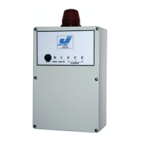
Turn on the control panel power, the self test should alarm for two
seconds then all alarms should return to normal state. The blue indicator
light should now indicate that there is power to the panel and circuits.
Check to make sure all system components are operational. If a pump is
connected to the system it may not immediately function depending on
additional float and timer control settings.
Test all inbound and outbound power with a multi-meter. All circuits
should have between 105 and 132 volts AC power supplied to the aerator,
compressor, and pump circuits.
If aerator circuits are set for timer intervals the cycle will begin with the on
aerator condition. To observe aerator timer intervals additional time will
need to be spent on site, or use the “Test Mode” to accelerate the timer
cycles.
If tests are not satisfactory recheck and correct the system wiring as
needed.
Once all checks are completed return the “Test Mode” to its normal
position and reset the control panel with the “Master Reset” switch.
Make sure to correct distributor information is on the front of the panel and
complete the control panel warranty card with the appropriate information.
 Loading...