5.0 Setup and assembly
5.1 Unpacking
Separate all parts from the packing material. Check
each part against sect. 5.2, Carton contents, and
make certain that all items are accounted for before
discarding any packing material. (Check grinder first
to verify if any parts have been pre-mounted.)
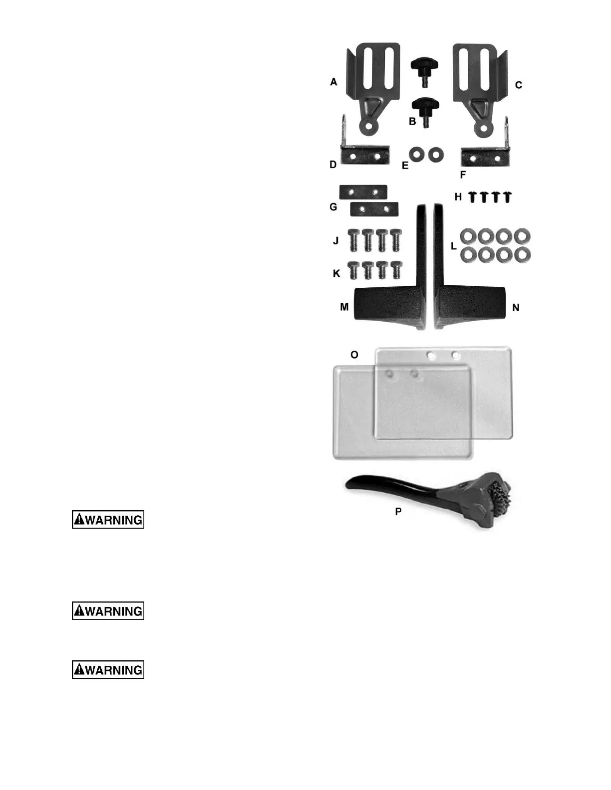
5.2 Carton contents
Refer to Figure 5-1.
1 ea Grinder (not shown)
1 ea Dust hose with T-connector (not shown)
1 ea Spark guard – Left (A)
2 ea Lock knob (B)
1 ea Spark guard – Right (C)
1 ea Eye shield bracket – Left (D)
2 ea Flat washer, 1/4" (E)
1 ea Eye shield bracket – Right (F)
2 ea Eye shield plate (G)
4 ea Truss head screw, 3/16 x 1/2” (H)
4 ea Hex cap screw, 3/8 x 3/4" (J)
4 ea Hex cap screw, 3/8 x 1/2" (K)
8 ea Flat washer 3/8” (L)
1 ea Tool rest – Left (M)
1 ea Tool rest – Right (N)
2 ea Eye shield (O)
1 ea Wheel dresser (P)
5.3 Tools required for assembly
Cross-point (Phillips) screwdriver
14mm (or adjustable) wrench
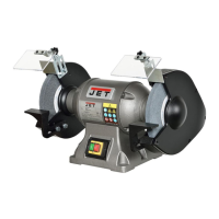
The IBG-8VS bench grinder requires only the
assembly of the eye shields and tool rests.
Additional tools may be needed for fastening the
grinder to a workbench or stand. For your safety, do
not plug the grinder into a power source until all
assembly and adjustments are complete.
Be sure that the bench grinder
is unplugged and the power switch is in the OFF
position. Do not plug in the grinder to power
until it is inspected for shipping damage, fully
assembled, and moved to its permanent
location. Failure to comply may cause serious
injury.
Do not operate this grinder
without all guards and shields in place and in
working order. Failure to comply may cause
serious injury.
Chipped or cracked wheels can
break up and cause serious damage to the
grinder and/or severe injury to the operator.
Regularly inspect wheels for damage.
Figure 5-1: Carton contents
5.4 Securing the grinder
To prevent the machine from moving during
operation, it should be securely mounted to a work
surface or grinder stand. Fasteners for mounting are
not included with the grinder.
1. Align the mounting holes on the grinder with
predrilled holes in a bench or grinder stand.
Figure 4-1 shows hole centers for mounting.
2. Insert M8 (or 5/16”) bolts through the holes and
tighten, using washers and nuts.
An optional pedestal stand (not included) is
available from JET for your grinder. See sect. 11.0.