7
6.0 Setup and assembly
Open shipping cartons and check that all parts are
intact. Report any damage immediately to your
distributor. Read the instruction manual thoroughly
for assembly, alignment, and maintenance
instructions.
6.1 Tools required
1 #3 cross point screwdriver
1 7/16” wrench
1 1/2" wrench
1 Combination square & straight edge
1 1/4” hex key
1 3/16” hex key
6.2 Shipping contents
1 XACTA Fence II
1 Front rail
1 Back rail
1 Guide tube
3 Black plastic end covers
1 Owner’s manual
1 Warranty registration card
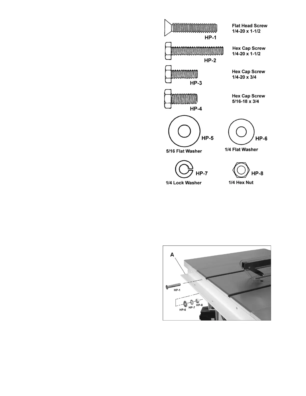
1 Hardware package (p/n XF12DX-HP)*
contains:
7 Flat head screws, 1/4 x 1-1/2 (HP-1)
5 Hex cap screws, 1/4 x 1-1/2 (HP-2)
7 Hex cap screws, 1/4 x 3/4 (HP-3)
2 Hex cap screws, 5/16 x 3/4 (HP-4)
2 Flat washers, 5/16 (HP-5)
24 Flat washers, 1/4 (HP-6)
19 Lock washers 1/4 (HP-7)
12 Hex nuts 1/4 (HP-8)
* Hardware package is shipped inside guide tube.
Contents are shown full scale in Figure 1.
6.3 Front rail installation
1. Identify the front rail (A, Figure 2), which is
2-1/2" x 2-1/2" with notches on one side and
countersunk mounting holes on the other side.
2. Lightly secure front rail (A) to table with seven
1/4 x 1-1/2 screws, flat washers, lock washers
and hex nuts (HP-1/6/7/8). Tighten just enough
to hold rail next to table but loose enough to
allow height adjustment.
Figure 1
Figure 2