PAGE 48 of 54
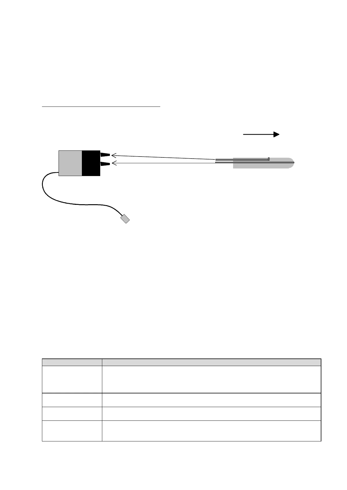
Connection diagram for the Airspeed Sensor:
Connect the air lines from the pitot tube to the airspeed sensor, using the 1/16
th
inch ID vinyl tubing
provided.
1 = Dynamic pressure input
2 = Static pressure input
Note: Tubing length and/or cross sectional area has no influence on measurement precision
Connect the Airspeed Sensor cable to the appropriate socket, where indicated on the ECU. The orange
wire is aligned to the pulse symbol. Once the Airspeed Sensor is connected, the ECU controls additional
functions:
under the Run menu, measurement of current air speed (“Airspeed”) and desired flight speed
(“SetSpeed”), can be displayed
under the Min/Max menu, the measured maximum speed (“MaxAirSpd”) and the average flight speed
(“AvgAirSpd”), can be displayed
under the Limits menu, speed limits and the parameters of speed regulation can be predetermined
Limits menu parameters assigned to the Airspeed Sensor:
Maximum allowed flight speed of the model, in km/h. If this speed is achieved,
turbine thrust is automatically reduced – to keep the model from exceeding the
maximum limit. This safety option is always active, despite the position of the AUX
switch.
Maximum flight speed value, in km/h, for the Speed Control mode. This value
corresponds to the speed at the maximum throttle stick position.
Minimum flight speed value, in km/h, for the Speed Control mode. This value
corresponds to the speed at the minimum throttle stick position.
Regulator speed, which sets the reaction time of the PID servo loop – much like a
sensitivity control in a gyroscope system.
Default value = 18 Increase this value, to increase reaction sensitivity.
 Loading...