Operation Manual
44
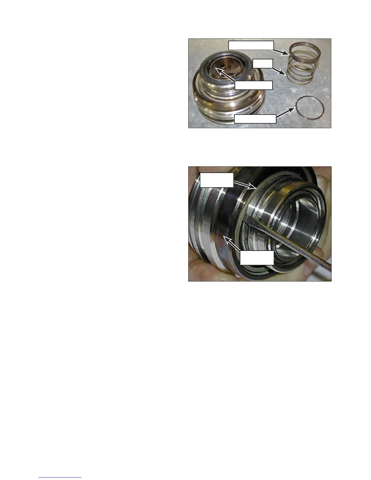
4. Remove the valve spring retainer and valve
spring (Figure 75).
5. Lift the assembly off of the suction valve and
set the suction valve aside.
6. Insert a small screwdriver under the dis-
charge spring (Figure 76). Carefully rotate the
screwdriver until the spring releases from the
groove.
Note: 3015 valves are equipped with a
retaining ring to secure the discharge
spring (Figure 77).
7. Remove the discharge valve and discharge
spring.
8. Inspect the valves. Refer to “Valve Inspection”
on page 50 for inspection criteria.
Figure 75: Retaining Ring and Spring Removal.
Spring Retainer
Spring
Suction Valve
Retaining Ring
Figure 76: Discharge Spring and Valve Removal.
Discharge
Spring
Discharge
Valve