Do you have a question about the Jetter JM-215B-480 and is the answer not in the manual?
Provides general information about safety regulations, standards, and user obligations.
Details measures for personal safety, including handling malfunctions and protective devices.
Highlights potential hazards during operation and after power disconnection.
Provides guidelines for electromagnetic interference (EMI) compatibility.
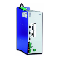
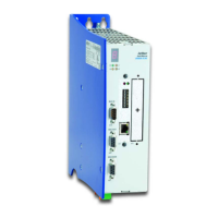
Lists all items included in the product package.
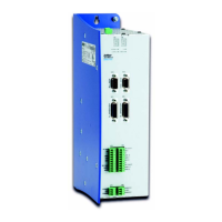
Details the physical mounting procedure and requirements for the servo amplifier.
Covers wiring, connections, and electrical safety aspects.
Highlights crucial safety precautions during the installation process.
Provides safety recommendations for the initial startup phase.
Details environmental and operational parameters like temperature, humidity, and altitude.
Specifies mechanical withstand capabilities and protection degrees.
Outlines electrical safety ratings and compliance standards.
Covers Electromagnetic Compatibility standards and requirements.
Details electrical characteristics, voltage, current, and supply requirements.
Explains methods for protecting the motor, including thermal sensors and I²t calculation.
Describes the motor control function, including PWM frequency.
Details the parameters for the speed controller.
Covers resolver and sine-cosine sensor specifications.
Specifies terminal and cable requirements for power supply.
Provides general remarks and specifications for motor connections.
Details specifications and cable requirements for resolver connections.
Details specifications and cable requirements for HIPERFACE connections.
Describes adapter, specifications, and connection diagram for Sin-Cos encoders.
Explains connections for external ballast resistors and DC link circuits.
Details digital input terminals and logic power supply specifications.
Explains terminal connections for digital outputs.
Specifies requirements for Jetter system bus cables.
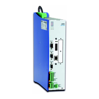
Explains the meaning and status of the device's LEDs.
Describes display states for normal and commissioning modes.
Lists and explains error codes, their response, and rectification steps.
Explains how to check for active alarms in the system.
Explains the functionality of the optional analog input card.
Lists technical specifications for the analog input.
Details connector and pin assignments for the analog input.
Explains the functionality of the optional Ethernet interface.
Details Ethernet cable types and connection methods.
Explains the function of logic circuit LEDs and DIP switches.
Describes methods for assigning an IP address to the device.
Introduces the Safe Standstill function for motor safety.
Provides safety requirements for controlling the safety circuit.
Outlines steps for testing the Safe Standstill function.
Details safety requirements and applicable standards.
Illustrates the block diagram of the Safe Standstill function.
Lists technical data and connection details for EnDat 2.2 input.
Details technical data and connection specifications for SSI input.
Lists technical data and connection specifications for incremental encoders.
Lists available documentation for download from Jetter AG.
Table outlining available optional features for the device.
Specifies the maximum torque for PE bolt tightening.
Illustrates the location of the PE bolt for proper tightening.
| Model | JM-215B-480 |
|---|---|
| Category | Amplifier |
| Power Output | 480W |
| Frequency Response | 20Hz - 20kHz |
| THD | <0.1% |
| Output Impedance | 4 - 8 Ohms |
| Cooling | Fan Cooled |