Do you have a question about the Jetter JetMove D203 and is the answer not in the manual?
Provides contact information for Jetter AG including phone, email, and website.
Explains the purpose and importance of the user manual for operating the servo amplifier.
Specifies the requirements for the motion system JetMove D203.
Explains the meaning of various danger, caution, and notice symbols used in the manual.
Adherence to applicable safety regulations and standards for user safety.
Usage according to operating instructions within specified values and conditions.
Specifies required qualifications for personnel involved in the product life cycle.
Operator cannot repair; device is maintenance-free except for optional controller.
Procedure for handling malfunctions: isolate from mains and report.
Instructions for proper grounding to ensure safety and prevent electric shock.
Details dangers from high operating voltage and hot surfaces during operation.
Warns about stored dangerous voltages in capacitors after power off.
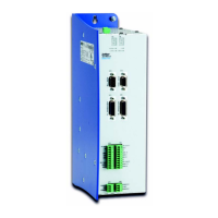
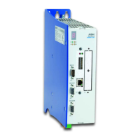
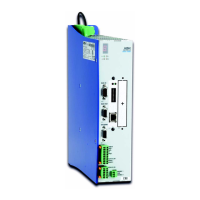
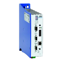
Lists items included with the digital servo amplifier and mating connector.
Details physical mounting requirements and procedures for the servo amplifier.
Provides guidelines for correct motor assignment, wiring, and cable selection.
Safety measures to be taken before energizing the device for commissioning.
Defines rated voltage supply, power connection type, and tolerances for the amplifier.
Describes methods for protecting the motor, including thermal sensors and I²t calculation.
Details the connection specifications for the 1-phase mains power supply.
Provides assignment and specification details for connecting the motor.
Specifies connectors and cables for connecting a resolver transducer.
Specifies connectors and cables for connecting a HIPERFACE encoder.
Specifies connectors and cables for connecting an incremental encoder.
Details specifications for digital inputs and logic power supply terminals.
Details the JX2 system bus for interlinking modules and peripherals.
Explains the function and specifications for connecting analog signals.
Details the function and color of status LEDs on the JetMove D203 amplifier.
Provides a fault message table with error numbers, types, and troubleshooting steps.
Explains how to interpret warnings indicated by the seven-segment display.
Instructions for correct wiring and connection of the integrated controller -JC24X.
Details the voltage range and current requirements for the JC24X power supply.
Provides technical data for the 16 digital inputs of the JC24X controller.
Provides technical data for the 8 digital outputs of the JC24X controller.
Details the Ethernet connection via RJ45 jack and cable types.
Explains four methods for assigning an IP address to the JC24X controller.
Details available options and configurations for JetMove servo amplifiers.
Lists part numbers for motor power cables with SC mating connectors, with and without brake.
Provides definitions for technical terms and abbreviations used in the manual.
An alphabetical index of topics and their page numbers for quick reference.