JetMove D203 Appendix
Jetter AG 139
Appendix C: List of Illustrations
Fig. 1: Double Earthing 16
Fig. 2: EMC-compliant shield connection of sub-D connectors 21
Fig. 3: Shielding of screw terminals to EMC standards 22
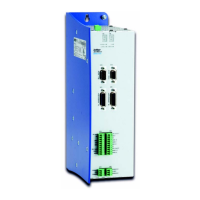
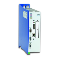
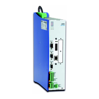
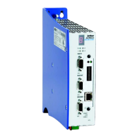
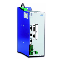
Fig. 4: Rear/front view of the JetMove D203 enclosure with mounting holes 25
Fig. 5: Physical dimensions of the JetMove D203 35
Fig. 6: Typical power dissipation of the ballast resistor 42
Fig. 7: Block diagram of drive controller structure 47
Fig. 8: Connection of the mains power supply 49
Fig. 9: Connection of motor lines 50
Fig. 10: View on the SC mating connector of the motor (internal thread M23) 52
Fig. 11: RC series mating connector of the resolver (internal thread M23) 58
Fig. 12: HIPERFACE connection with set supply voltage 61
Fig. 13: RC series HIPERFACE mating connector (internal thread M23) 62
Fig. 14: Sin-cos encoder connection of +5 V supply voltage 64
Fig. 15: Sin-cos encoder connection with a feedback control of the supply voltage
64
Fig. 16: Sin-cos encoder connection, also setting the supply voltage 65
Fig. 17: Incremental encoder connection of a +5 V supply voltage 68
Fig. 18: Incremental encoder connection with feedback controlling of the supply
voltage 68
Fig. 19: Connection diagram JM-D203, type of position transducer: Resolver 87
Fig. 20: Connection diagram JM-D203, type of position transducer: HIPERFACE
88
Fig. 21: Connection diagram JetMove D203, of the following option: S1 89
Fig. 22: JM-D203-JC24X: Connection of the input and output voltage supply 95
Fig. 23: LEDs of the digital inputs of the -JC24X 97
Fig. 24: External circuit of the digital inputs 4 and 13 99
Fig. 25: LEDs of the digital outputs of the -JC24X 101
Fig. 26: External circuit of the digital outputs 3 and 5 103
Fig. 27: Ethernet connection 105
Fig. 28: Ethernet connection between PC and JetControl 106
Fig. 29: Ethernet connection between -JC24X and switch 106
Fig. 30: Ethernet connection from switch to switch 107
Fig. 31: Status LEDs 109
Fig. 32: Settings of the mode selector S11 111
Fig. 33: IP address pattern 114
Fig. 34: Determining the IP address based on address switch positions 115
Fig. 35: Setting a specific IP address 116
Fig. 36: Installing the Anybus-CC: Prying the break-away shield 126
Fig. 37: Series of illustrations: Inserting the Anybus-CC module 128