Step 1: Connect the power cable of the device with the B+, ACC, and GND wires from
the vehicle fuse box. Refer to Figure ① for the location.
Step 2: Route the power cable along the A pillar to the top center of the front wind
shield. Refer to the dotted line in Figure ②.
4.6. Device testing
1. Check the power cable connection: Normally, when the vehicle is in the ACC ON
state, the power indicator (red) of the device will light on; otherwise, the power
indicator will be off.
2. Check the GNSS function of the device: Normally, when the vehicle's ignition is
turned to the ON position, the GNSS indicator (green) will flash; you can drive
your vehicle to an open area and wait for one minute, then the GNSS indicator
will change to solid on.
3. Check the data communication function of the device: Normally, when the vehicle's
ignition is turned to the ON position, the cellular indicator (blue) will flash; you can
drive your vehicle to a place where the cellular signals are good, then the cellular
indicator will change to solid on.
4. Check the cameras: Log in to the designated mobile app and go to the live video
interface. If you can switch between cameras, then the cameras are working
properly. You can manually adjust the capture angle of the cameras according to
actual conditions.
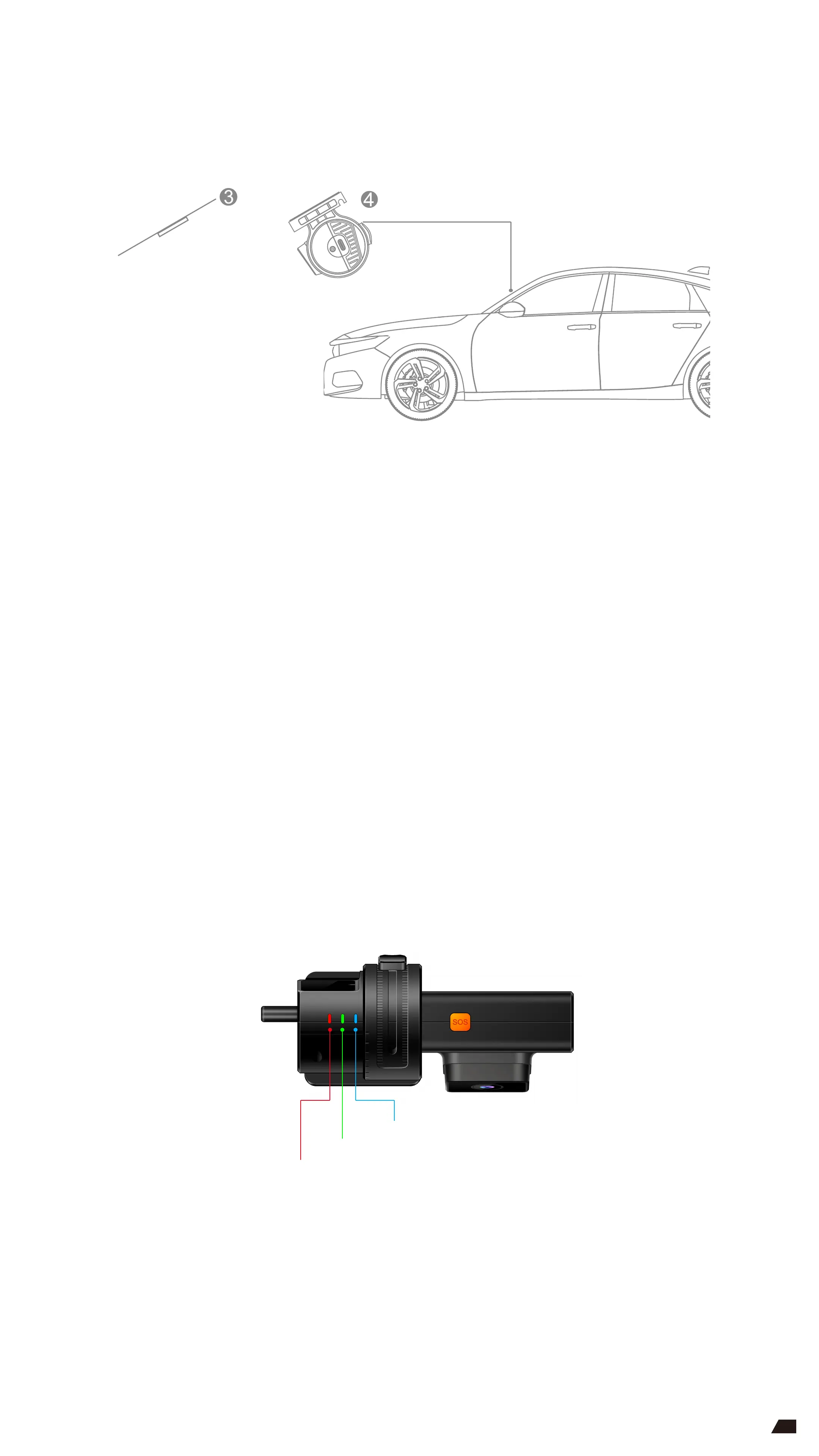
Step 3: Attach the mount base
Select a suitable position on the front windshield. The recommended position is
one that is to the left side behind the rearview mirror (near the driver's seat);
Clean the mounting position to ensure there is no dust or smudges; Remove
the protective film from the 3M double-sided adhesive tape on the mount base
and attach the base to the mounting position, as shown in Figure ③.
After attaching the base, apply a moderate amount of force to enhance the
contact and squeeze out the air to ensure that the mount base stays in place
without falling.
Step 4: Mount the device on the base and adjust the front camera so that it is facing for
ward horizontally, as shown in Figure ④. Tighten the adjustment screw of the base
and connect the power cable to complete the installation.
GREEN: GNSS indicator
BLUE: Cellular indicator
RED: Power indicator
7
 Loading...