EN | Page 8
|
E-Sub
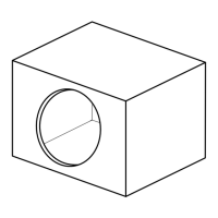
SPECIAL CONSIDERATIONS FOR BUILT-IN INSTALLATIONS
The E-Sub can be integrated into custom cabinetry by following a few simple
guidelines.
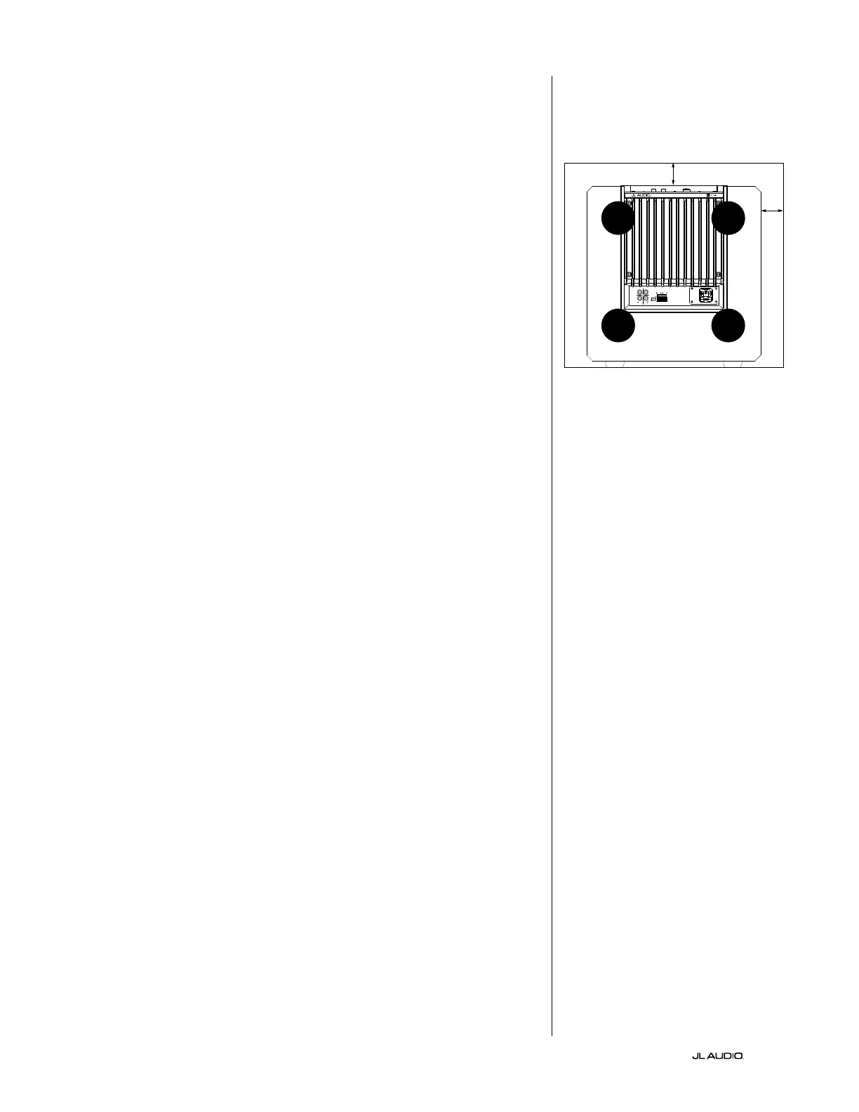
1. Allow 4 inches (10 cm) of clear space behind the E-Sub’s amp panel for
adequate cooling and connector clearance.
2. On all other sides (except the bottom), allow at least 2 inches (5 cm)
clearance for adequate ventilation.
3. While the E-Sub generally runs only warm during spirited operation, we do
recommend that adequate heat vents are included in any custom cabinet which
encloses the E-Sub. A pair of 3 inch (7.5 cm) diameter vents near the bottom of
the cabinet and near the top of the cabinet, will allow cool air to circulate over
the amp panel of your E-Sub subwoofer system keeping it cool and happy.
4. Your E-Sub subwoofer is capable of moving substantial quantities of
air. If the front of the E-Sub is covered by a custom grille, the grille
must have AT LEAST 85 square inches (548 sq.cm.) of vent area for
the e112, and AT LEAST 60 square inches (386 sq.cm.) for the e110.
These areas are equal to the woofer cone area for each model and will
ensure that the E-Sub’s output is not choked by the custom cabinet.
CH. 2
(
R
)
Grounded
Isolated
CH. 1
(
L
)
HIGH LEVEL INPUTS
SERIAL NUMBER:
Warranty void if serial number is
removed, altered or defaced.
LINE
OUTPUTS
LL
RR
LINE
INPUTS
Built in USA
with domestic and
imported components
VENT VENT
2 in. min.
2 in.
min.
Rear-view of cabinet install:
VENT VENT