 Loading...
Do you have a question about the JL Audio e112 and is the answer not in the manual?
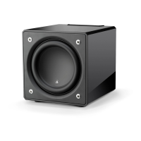
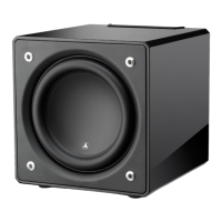
| Type | Powered subwoofer |
|---|---|
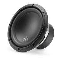
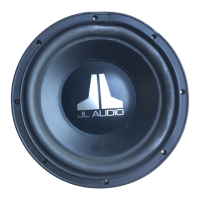
| Driver Size | 12 inches |
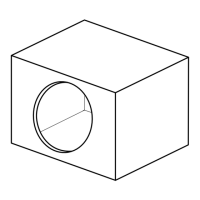
| Enclosure Type | Sealed |
| Power Handling (RMS) | 600 Watts |
| Power Handling (Peak) | 1200W |
| Inputs | L/R RCA, L/R XLR |
| Impedance | N/A (Powered) |
Read and retain all safety and operating instructions for proper use.
Avoid water, ensure ventilation, and keep away from heat sources.
Proper power connection and protection against lightning and surges.
Prevent object/liquid entry; service for damage; limit user servicing.
Avoid overloading outlets, ensure grounding, heed high sound pressure warnings.
Improves dynamic motor behavior, reduces distortion, and ensures faithful transient reproduction.
Enhances cone/spider junction stability and excursion control for better performance.
Ensures quiet lead-wire behavior, reducing distortion and improving reliability.
Combines advanced driver, amplifier, and enclosure for exceptional low-frequency performance.
High excursion driver and powerful switching amplifier for accurate bass reproduction.
Robust cabinet construction and versatile input/output options for system integration.
How room dimensions create standing waves, peaks, and dips affecting sound.
Experiment with positions to find best bass response and avoid room modes.
Place near front speakers, avoid windows, experiment with distance from walls.
Diagrams showing placement for 'more intense' or 'smoother' bass response.
Identifies 'best' and 'compromised' seating positions for accurate bass.
Minimum clearance for cooling and ventilation around the E-Sub amplifier panel and sides.
Specify required vent area for custom grilles for optimal airflow.
Diagrams for placing two E-Subs in various room configurations for optimal bass.
Recommends experimentation and professional calibration for best results.
Diagrams illustrating recommended placement for three E-Subs.
Diagrams showing optimal placement for four E-Subs for smoothest bass response.
Emphasizes experimentation and professional calibration for multi-subwoofer systems.
Warning about subwoofer weight and recommendation for a second person.
Step-by-step guide for safely removing the subwoofer from its packaging.
Retain packaging for safe transportation and future service needs.
Identifies the location and labels of controls on the top panel.
Lists controls and their corresponding page numbers for detailed explanations.
Diagram showing the rear panel layout and connection points.
Details on Line Inputs, High Level Inputs, Line Outputs, and AC Connector.
Explanation of the switch for managing ground loop noise.
Explains the three positions (Off, On, Auto) and LED states for the power switch.
Details on adjusting the subwoofer's output level relative to the audio system.
Determines operating mode of the built-in active crossover (Off/On).
Sets the crossover frequency from 25 Hz to 130 Hz for seamless integration.
Selects normal (0 deg) or reversed (180 deg) signal polarity for optimal transition.
Adjusts subwoofer timing relative to main speakers for smooth sound integration.
Experiment with phase settings using source material for best midbass response.
Using RCA connectors for stereo or mono input, including summing behavior.
Helps eliminate hum by selecting input mode for line-level signals.
Connecting via speaker outputs when line-level is unavailable.
Using outputs for pass-through or high-pass filtered signals.
Information on the IEC connector, voltage, and power cord usage.
Warning about potential circuit breaker tripping with high current draw.
Connecting a single E-Sub to a home theater receiver using line-level output.
Setting the E-Sub's crossover to 'Off' when using receiver bass management.
Connecting multiple E-Subs using pass-through line outputs.
Ensure crossover is 'Off' for pass-through signal functionality.
Using Y-adaptors or multiple subwoofer outputs for system connection.
Connecting one E-Sub in mono to a 2-channel system using line inputs.
Engaging the crossover creates a two-way system for improved performance.
Connecting two E-Subs in stereo to a 2-channel system for enhanced bass.
Engage crossover on each E-Sub for optimal two-way performance.
Connecting E-Sub using receiver speaker outputs when line-level is unavailable.
Summing inputs and crossover effect on E-Sub with high-level connections.
Configure speaker size, distance, level, and tone controls on your receiver.
Set crossover frequency and subwoofer output level on your processor.
Set Power switch to 'On' and Crossover to 'Off' or 'On' with 80Hz.
Set Polarity switch to '0' and Phase knob to '0' degrees.
Adjust subwoofer level with other speakers using receiver or Master Level knob.
Fine-tune polarity and phase for natural sound and smooth transition.
Experiment with placement for optimal bass smoothness and performance.
Avoid placing items on subwoofer; magnetic shielding and TV proximity.
Auto mode power consumption; unplugging during storms or absence.
E-Sub is for dry, indoor environments only; not for outdoor or pool deck use.
Dusting with microfiber cloth for gloss-black and vinyl-veneer models.
Using wax for gloss-black, damp cloth for vinyl-veneer, avoiding harsh chemicals.
Checks for power, receiver settings, and cable connections; adjusting level.
Addressing hums, muddy bass, or audible output outside the house.
Humorous advice for managing loud bass impact on neighbors.
Detailed technical specs for the E110 model, including dimensions and weight.
Detailed technical specs for the E112 model, including dimensions and weight.
Summary of features like inputs, power modes, crossover, and amplifier topology.