Thank you for purchasing a JL Audio amplifier for
your sound system.
Your amplifier has been designed and manufactured to exacting
standards in order to ensure years of musical enjoyment. For maximum
performance, we highly recommend that you have
your new amplifier installed by an authorized JL Audio dealer. Your
authorized dealer has the training, expertise and installation equipment
to ensure optimum performance from this product. Should you
decide to install the amplifier yourself, please take the time
to read this manual thoroughly to familiarize yourself
with its installation requirements and setup procedures.
If you have any questions regarding the instructions in this
manual or any aspect of your amplifier’s operation, please contact your
authorized JL Audio dealer for assistance. If you need further assistance,
please call the JL Audio Technical Support Department
at technical@jlaudio.com or call (954) 443–1100 during business hours.
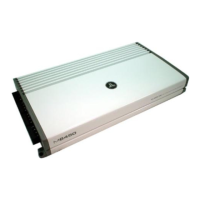
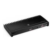
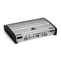
OWNER’S MANUAL
500W Full-Range 4-Channel Class D Amplier
What’s Included
(1) Amplifier
(4) Stainless steel mounting screws
(1) User manual
Product Description
This is a four-channel, full-range audio amplifier utilizing Class D technology for
all channels.
Installation Applications
This amplifier is designed for operation with 12 volt, negative-ground electrical
systems. Using this product in systems with positive ground and/or voltages
other than 12V may result in damage to the product and will void the warranty.
This product is not certified or approved for use in aircraft.
Safety Considerations
• Whenever possible, mount the amplifier in a dry, well-ventilated location
that does not interfere with other factory installed electronic devices. If a dry
environment is not available, a location that is not exposed to heavy splashing
may be used.
• While this amplifier is designed to be water-resistant, it should never be
submerged under water or subjected to high-pressure water spray.
Do not install where it will be directly exposed to the elements.
• Do not mount the amplifier in the engine compartment or in any areas of
extreme heat.
• Securely mount the amplifier so that it does not come loose in the
event of a collision/sudden jolt or as a result of repeated vibrations during
normal operation.
• Check before drilling to make sure that you will not be drilling into an exterior
panel/hull, fuel tank, gas/brake line, wiring harness, or other vital system.
• Do not run system wiring outside or underneath the vehicle/vessel. This is an
extremely dangerous practice, which can result in severe damage/injury.
• Protect all system wires from sharp edges (metal, fiberglass, etc.) by
carefully routing them, tying them down and using grommets and loom
where appropriate.
• Secure all wiring as needed, using cable ties or wire clamps to protect them
from moving parts and sharp edges.
IPX7 Water Resistance Rating
This product has been tested to withstand immersion in water, up to 1 meter
(3.28 ft.) deep, for up to 30 minutes (with control panel cover properly installed).
Note - while designed to be water resistant, this product should never be
submerged under water for prolonged periods or subjected to activity that
creates pressure on it that exceeds its depth rating.
Installation Procedure/Connections
1. Disconnect the NEGATIVE battery post connection and secure the discon-
nected cable to prevent accidental reconnection during installation. This is
an essential safety precaution during installation!
2. Connect the RED power lead to the positive (+12V) battery post. 4 AWG is
the minimum power wire size for this amplifier.
3. An appropriate fuse (sold separately), such as the JL Audio Water-Resistant
Master MAXI™ Fuse Block (XD-MFBW-MAXI), at the main power wire(s) to
the amplifier(s) is vital for vehicle/vessel safety. This fuse must be installed
within 18 inches (45 cm) of the positive battery post connection. If this is
the only device connected to this main wire, use a 50A fuse. Do not install
the fuse until the power wire has been securely connected to the amplifier.
4. Connect the BLACK negative ground lead to a clean, solid metal grounding
point near the amplifier. This can be to metal chassis ground, if available. If
no metal chassis ground is available, it may be necessary to make this con-
nection to the NEGATIVE battery post. 4 AWG is the minimum ground wire
size for this amplifier. All ground connections (source unit and amplifi-
ers) should be made at the same location.
5. Connect the BLUE remote turn-on lead to the source unit’s positive (+12V)
remote turn-on output. If your source unit does not have a dedicated
remote turn-on output, the amplifier’s turn-on lead can be connected to
+12V via a switch that derives power from an ignition-switched circuit.
6. Signal Input (Low-Level): Connect the amplifier’s RCA input jacks to the
source unit’s preamp level output jacks.
7. Signal Input (Hi-Level): If your source unit does not offer preamp level signal
outputs, you can splice the speaker output wires of the source unit onto a
pair of RCA plugs for each input pair or use the JL Audio ECS Speaker Wire
to RCA adaptor (XD-CLRAIC2-SW). Make sure to observe correct polarity in
making “Hi-Level Input” connections. Failure to do so will result in a loss of
signal (poor performance).
8. Connect the speaker output leads to the corresponding speaker wires.
9. Make necessary adjustments to the filter controls and input sensitivity.
WARNING! Failure to make safe, tight, high-integrity power connections
can result in fire and extensive damage!
Control Setting Mode / Function
Channel Mode
2CH
#1) 4 Stereo Outputs (non-fading)
Use Front
Inputs Only
#2) 2 Bridged Mono Outputs
3CH
#1) 2 Stereo Front + 2 Mono Rear Outputs
Use Front
Inputs Only
#2) 2 Stereo Front + 1 Bridged Mono Rear Output
4CH
#1) 4 Stereo Outputs (fading) Use Front and Rear Inputs
#2) 2 Bridged Stereo Outputs
Left to Both
Front Inputs
Right to Both
Rear Inputs
Front
or
Rear
Input
Voltage
Low RCA/Preamp Level Range (250 mV - 4 V)
High RCA/Preamp or Speaker Level Range (750 mV - 15 V)
Filter
Mode
Off Full-Range Operation of Input Signals
HP
(High-Pass) Configures Filter to Attenuate Frequencies BELOW
the Selected Filter Frequency
LP
(Low-Pass) Configures Filter to Attenuate Frequencies ABOVE
the Selected Filter Frequency
Filter
Freq.
Variable
Adjusts the filter cutoff frequency of the selected Filter Mode,
variable from 35-300 Hz, 12 dB/Octave
Input
Sens.
Variable
Adjusts the input stage of each pair of amplifier channels to
match the source unit’s output voltage for maximum clean
output (refer to Appendix A)
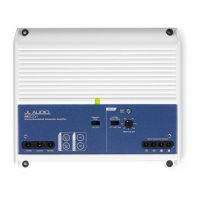
Control Panel Settings and Adjustments
The amplifier’s settings and controls are located on the bottom panel beneath a
gasketed, protective cover. Remove the four Phillips head screws from the center
panel to access the controls and make adjustments. Replace cover when finished
and mount the amplifier.
Specications MX500/4
Rated RMS Power @ 14.4V,
<1% THD+N
70W x 4 @ 4 Ω 90W x 4 @ 3 Ω
125W x 4 @ 2 Ω 250W x 2 @ 4 Ω Bridged
Rated RMS Power @ 12.5V,
<1% THD+N
55W x 4 @ 4 Ω 70W x 4 @ 3 Ω
90W x 4 @ 2 Ω 180W x 2 @ 4 Ω Bridged
Frequency Response 20 Hz - 20 kHz (+0, -1dB), 6.3 Hz - 30 kHz (+0, -3dB)
S/N Ratio, A-weighted,
20 kHz noise bandwidth
88 dB (Referred to rated power), 68 dB (Referred to 1 W)
Damping Factor >92 / 50 Hz @ 4 Ω, >43 / 50 Hz @ 2 Ω
Input Voltage Range 250 mV - 4 V (Low) or 750 mV - 15 V (High)
Filter Modes Low-Pass or High-Pass, defeatable
Filter Freq. Range, Slope 35 - 300 Hz, 12 dB/Octave
Detented Filter Frequency
Potentiometers
35, 80, 135, 300 Hz (Calibrated)
Input Mode Switch 2 / 3 / 4 Channel
Min Power/GND Wire 4 AWG
Fuse Rating 50A
Dimensions 9.33 in x 4.50 in x 1.77 in / 237 mm x 114.5 mm x 45 mm
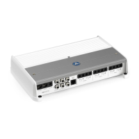
Status LED’s / Protection Circuitry
There are two status indicator lights on the wiring end panel of the amplifier.
1. “POWER” (Green): Lights to indicate that the amplifier is turned on and
operating normally.
2. “PROTECT” (Red): Lights to indicate the amplifier’s protection circuitry
has been activated to prevent product failure due to thermal overload,
over current or short-circuit to the amplifier’s outputs. When this pro-
tection mode is activated, the amplifier will shut down to protect its
circuitry. When the problem is corrected, the amplifier will return to
normal operation and the “Protect” LED will shut off. Connecting the
speaker outputs to impedances lower than 2 ohms stereo (4 ohms
bridged) will also cause this protection mode to activate.
POWER
(Green LED)
PROTECT
(Red LED)
Status Note
ON OFF Normal Operation
OFF ON Thermal Protection Lasts until temp cools to normal
OFF/ON ON/OFF Over Current Green/Red LEDs alternate for 1 second
OFF ON Short Circuit Possible audible “popping” noise
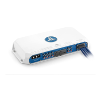
Remote Turn-On
High <or> Low-Level Inputs Speaker
Outputs
(selectable via Input Voltage Switch
for each channel pair)
[FR–]
[FR+]
[RL–]
[RL+]
[RR–]
[RR+]
[FL–]
[FL+]
[REAR IN]
Source
[REM]
Battery
Fuse
(not included)
[+12V]
[GND]
[FRONT IN]
Label Wire Color Description
+12V Red Positive (+12V) Power Connection
GND Black Negative (GND) Ground Connection
REM Blue Positive (+12V) Remote Turn-On Input
FL+ White
Ch. 1
output
(+) Positive Front Left Speaker Front Bridged (+)
FL– White/Black (–) Negative Front Left Speaker
FR+ Gray
Ch. 2
output
(+) Positive Front Right Speaker
FR– Gray/Black (–) Negative Front Right Speaker Front Bridged (–)
RL+ Green
Ch. 3
output
(+) Positive Rear Left Speaker Rear Bridged (+)
RL– Green/Black (–) Negative Rear Left Speaker
RR+ Purple
Ch. 4
output
(+) Positive Rear Right Speaker
RR– Purple/Black (–) Negative Rear Right Speaker Rear Bridged (–)
Label Plug Description
FRONT
IN
White RCA Ch. 1 / Front Left Channel Signal Input
Red RCA Ch. 2 / Front Right Channel Signal Input
REAR
IN
White RCA Ch. 3 / Rear Left Channel Signal Input
Red RCA Ch. 4 / Rear Right Channel Signal Input
Connections
IPX7
WATER
RESISTANT