to the controller, and please pay attention to the distinction between positive and
negative electrode, if the positive and negative connection errors may cause
permanent damage to the load, because you do not necessarily have protection
against reverse loads.The controller can connect two road load, if there are two
road load needs to connect, please positive screwed together two loads
connected to the controller L+ terminal and the negative electrode are connected
to the controller L1-, L2- terminals.After connection, observe whether the load is
normal work, if don't work properly, please observe whether the controller panel
out light is flashing, If flashing battery under-voltage, need to charge to work
properly.
⑦Choose appropriate copper core cable to connect the solar panels and solar
controller terminal S+ S-, and please pay attention to the distinction between
positive and negative electrode,If the positive and negative reversed, controller to
start the reverse connect protection (premise is in front of the 6 steps is
right).Connect the correct logo is the controller panel at the charge red light will
light (the premise must be during the day).
⑧Choose appropriate copper core cable to connect the unloading and controller
unloading terminal, no positive negative distinction.
⑨Choose appropriate copper core cable to connect the fan and controller fan
terminal, if it is a three-phase ac fan, three terminal non-electrode distinguish, if it
is a dc fan, connection in any controller fan three terminals of any two of the
above.Please select when install the fan under the condition of low wind speed,
so as to avoid accidents.
2.Operation debugging
(1)Status Indication:
4 - 2
9
(2)Button instructions
4-2
As shown in figure 4-2,
Button①:Press this button to enter setup interface or switch set up program;
Button②:Click this button to switch down in page views,in the setup interface
click this button is used to reduce the parameter values, step 0.1 V.
Button③:Click this button to switch up browsing on page views,in the setup
interface click this button is used to increase the parameter value, step 0.1 V.
Button④:Click this button to exit the setup interface, and save the parameters.
(3)LCD screen (the default interface)
To the user in accordance with the specifications, general automatically entered
into the following interface (figure 4-3) :
4-3
on behalf of the display Battery voltage at this time, digital is the
Battery voltage readings;
represents the current day (if it is night, the icon into );
Two represent the charging and discharging, for charging, have the
current will show effect, when there is no current or current is very small, the label

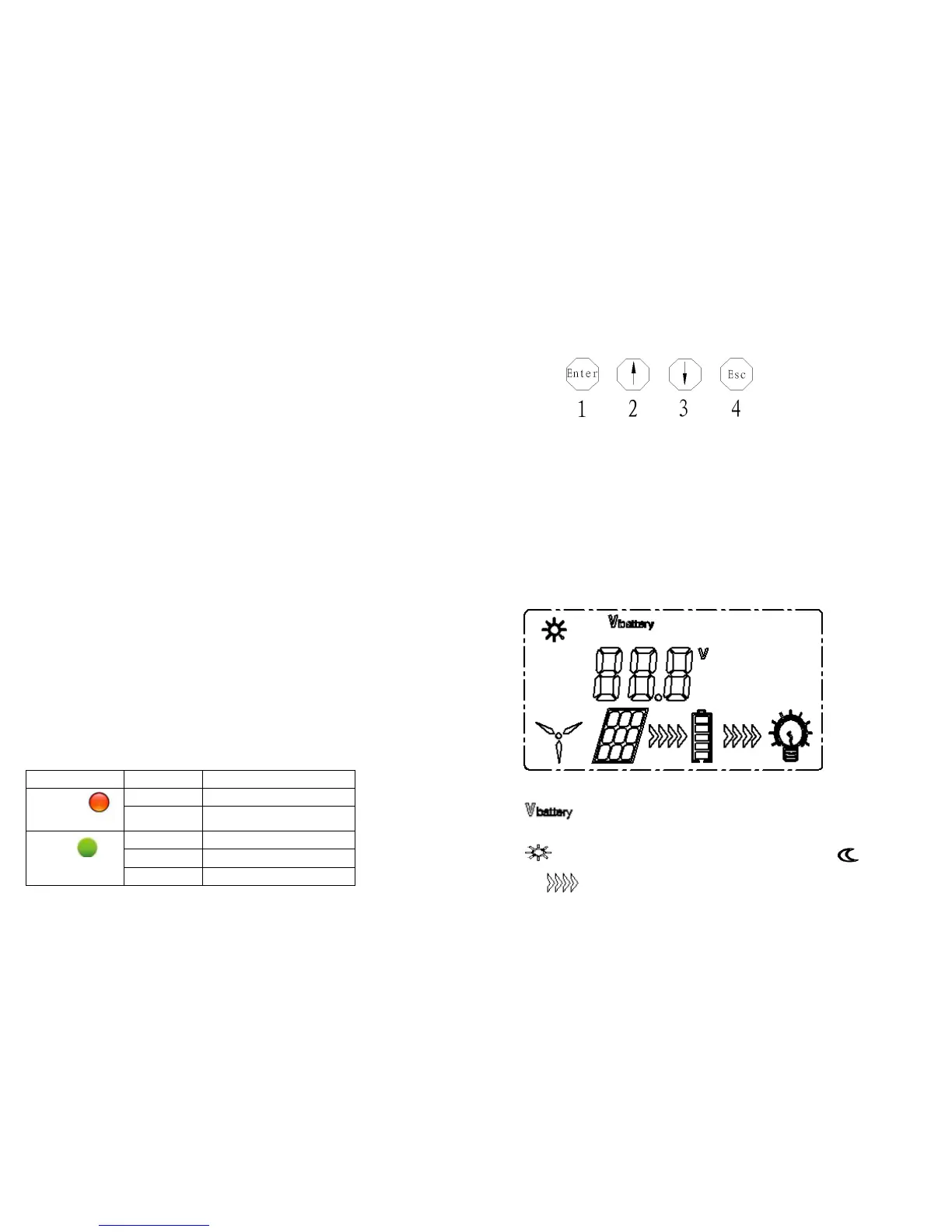 Loading...