9
Joerns® Advanced Support Surfaces
Dolphin Fluid Immersion Simulation® Systems
© 2014 Joerns Healthcare • 6110109 RevG • 14-2640
In the Bed position, the system operates normally,
but when switched to the Chair/Stretcher position,
the timing cycles change to allow use on a specialty
surface.
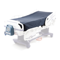
Using the specialty surface allows the system to be
moved from the patient bed to a wheelchair cushion
or stretcher pad, providing the normal functions of the
system.
Alarm (Figure 4)
The warning or alarm subsystem consists of LED’s
and a beeper which displays red and beeps when a
fault condition occurs.
A fault condition is considered to be any of the
following conditions:
• Pressure too hard for more than a 10 second period
• Pressure too soft for more than a 10 minute period
• Differential error between “Comfort Adjust setting”
and “Auto Feedback” for more than a 30 minute
period
The beeper may be manually disabled for up to 30
minutes by pressing the yellow Alarm button.
This feature avoids annoyance while a fault is being
corrected, but will automatically re-assert itself after 30
minutes time, or until the fault is corrected. The LED’s
continue to function normally, regardless of the Alarm
on/off state.
Lock (Figure 4)
The Lock button and associated yellow LED permit
the entire control panel to be locked from further
adjustments.
When locked, pressing the Lock button again restores
normal operation and the yellow LED is extinguished.
Battery Indicators (Figure 4)
The Battery indicator will blink when the AC power has
been interrupted and the control unit is running on the
battery back-up power.
The Battery Low indicator will blink when the battery
back-up is at the end of its charge life. Plug control
unit back into a power outlet as soon as possible to
resume normal operation. Upon restoration of AC
power, the battery back-up will begin the recharge
process. Note: To ensure the battery recharges when
connected to AC power, the Storage Switch must be in
the Battery On position.
Figure 6
Figure 5
Immersion Prole Window (Figure 5)
The Immersion Prole indicates the system response
to patient initial positioning and position change. When
in optimal position, the green LED will illuminate.
When the system is in transition, the yellow/red LEDs
will illuminate. The Dolphin FIS System will recreate
the optimal prole based on individual patient body
characteristics. No manual adjustment is needed.
Comfort Controls (Figure 6)
Autorm
The Autorm mode is strictly used for patient transfers,
repositioning and to quickly inate the surface when it
has not been in use.
Caution: The System should never be left in Autorm
mode while a patient is on the surface outside of
transfers or repositioning. Autorm is not a therapy
mode.
To override the Autorm mode, press the Autorm
button again.