9
LEVEL ADJUSTMENT
LED is red
LED is green
LED is acitvated
LED is green
LED is green
LED is red
LED is green
1
2
3
4
5
6
78
9
Level
Note:
'
30' is for maximum gain.
'
18' indicates 12 dB attenuator.
Filter & Input Selection
Filter & Input Selection
Filter & Input Selection
Level
Level
VHF
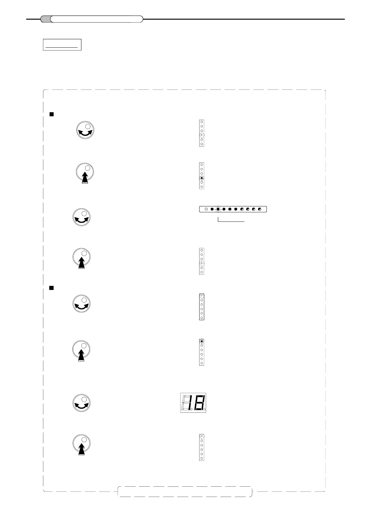
- Turn the button to select cluster 2.
- Push the button to confirm.
- Turn the button to select the
Level
mode.
- Push the rotary button to enter the selected mode.
- Turn the button to set the level, variable from 30 dB to 0 dB.
Level setting
- Push the button to confirm.
Repeat this section to set all levels
To set the level.
- Select the desired cluster.
Example : setting the level of cluster 2
- Turn the button to select the
Filter & Input Selection
mode.
- Push the rotary button to enter the selected mode.


 To Next Page