Model EELR537A
Installation, Operation and Maintenance
Page 4
Rev. 09/16/2021
EELR537A-IOM.
doc
RECEIVING
The shipment should be thoroughly inspected as
soon as it is received. The signed bill of lading is
acknowledgement by the carrier of receipt in
good condition of shipment covered by our
invoice.
If any of the goods called for on this bill of lading
are shorted or damaged, do not accept them until
the carrier makes a notation on the freight bill of
the shorted or damaged goods. Do this for your
own protection.
NOTIFY
Snap-on Equipment Customer
Service
AT ONCE if any hidden loss or damage
is discovered after receipt.
IT IS DIFFICULT TO COLLECT FOR LOSS OR
DAMAGE AFTER YOU HAVE GIVEN THE
CARRIER A CLEAR RECEIPT.
File your claim with
Snap-on Equipment
promptly. Support your claim with copies of the
bill of lading, freight bill, and photographs, if
available.
Component Packing List
PART #
QTY/ LIFT
DESCRIPTION
JSJ6-02-00 1
Power Column
Assembly
JSJ6-02-00f 1 Idler Column Assembly
JSJ6-03-00 1 Overhead Assembly
E12-HW-A 1 Hardware Box
JSJ6-02-02-01 2 Column Extension
JSJ6-09-00 4 Arm Assemblies
JSJ6-04-00 2
Synchronizer Cable
Assembly
E12-HP 1 Hydraulic Hose Pack
JSJ5-02-14A 2 Lock Cover
INSTALLATION
SAFETY REQUIREMENTS FOR INSTALLATION AND
SERVICE
Refer to ANSI/ALI ALIS (current edition)
I
MPORTANT: Always wear safety glasses while installing lift.
TOOLS (MINIMUM REQUIRED)
a. Tape measure, 16ft
b. Chalk line
c. 4ft level
d. 10” adjustable wrench
e. Metric open end wrenches 10mm, 13mm,
14mm, 15mm, 17mm, 18mm, 19mm and
24mm
f. Metric Allen Wrenches 4mm, 5mm, 6mm,
and 8mm.
g. Needle Nose pliers
h. Snap Ring pliers
i. Hammer drill with 3/4” diameter carbide
tipped bits
j. 2lb hammer
k. Torque wrench: 150 foot pounds minimum
with 1 1/8” socket
l. 12 ft. Step ladder
m. Anti-Seize lubricant (for arm pins and foot
pad screw threads and stop rings)
L
AYOUT
1) Layout the service bay according to the
architect’s plans or owners instructions (see
Fig 1b). Failure to install in this orientation
can result in personal and property
damage. Be certain that the proper
conditions exist, see page 3.
2) Attach bolt-on parts to column extensions as
shown in Fig. 5 and assemble to columns
using M12 x 30 Hex bolts. Ensure power
extension assembly is bolted to power
column. NOTE: Install Nut and Washers on
exterior of the assembly
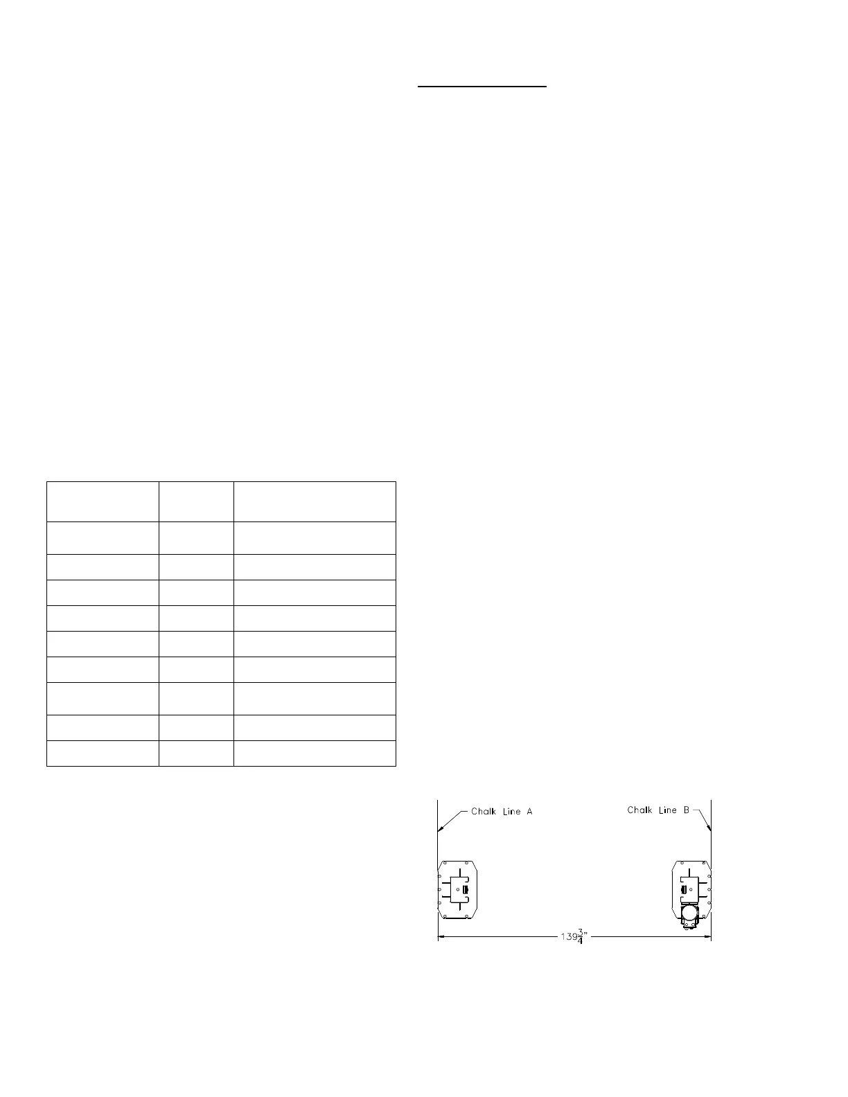
3) Using the Overall Width (C) Dimension from
Fig. 1, chalk two parallel lines on the floor
within 1/8” tolerance. Erect both column
assemblies. Align the base plate edges to the
chalk lines.
Fig. 1 –
Column Layout