G
eneral Instructions
1. Study the engineering layout drawing to confirm the proper seal
arrangement for the pump being used. Type 5620 seals are
designed for versatility and can be assembled in various ways.
The following instructions describe the standard configurations.
2. To assure satisfactory operation, handle seal with care. Take
particular caution to see that the lapped sealing faces are not scratched
or damaged.
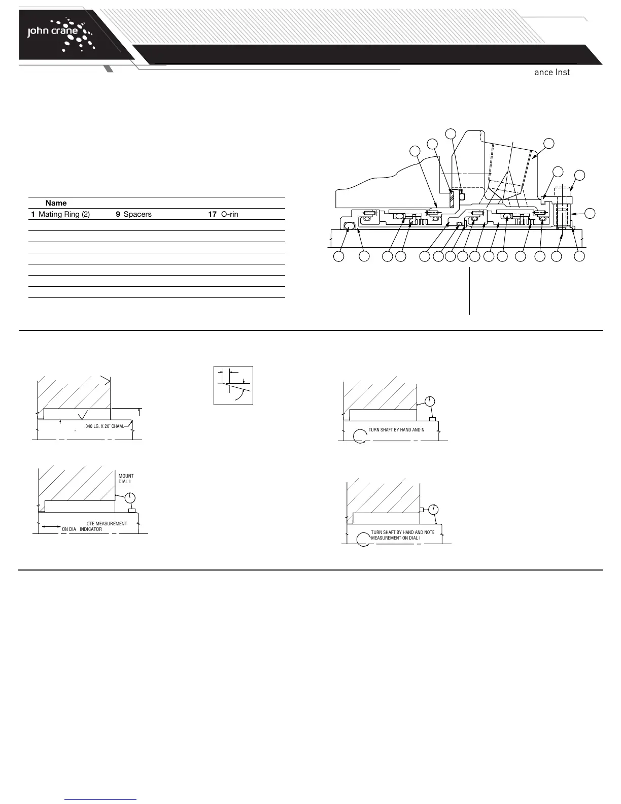
Typical Type 5620 or 5620P Dual Cartridge
Seal Arrangement
6
5
19
13 17 412022 21 312 815
14
16
18
11
9
10
7
2
Preparing the Equipment
1. Check seal chamber dimensions and finishes.
2. Measure axial end play: Sizes to 3.000"= 0.003" FIM max.
3.000" and greater = 0.005" FIM max.
3. Determine squareness of seal chamber face to shaft:
Rotating Mating Ring
Sizes to 3.000"= 0.005" FIM max.
3.000" and greater = 0.007" FIM max.
Rotating Seal Head
Sizes to 3.000"= 0.002" FIM max.
3.000" and greater = 0.003" FIM max.
4. Measure shaft runout: Sizes to 3.000"= 0.002" FIM max.
3.000" and greater = 0.003" FIM max.
Inboard
Side
Outboard
Side
Type 5620 Dual O-ring Cartridge Seal Assembly
Assemble the Type 5620 as follows, referring to the applicable engineering
layout drawing.
NOTE: These instructions apply to a rotating mating ring configuration
inboard and a rotating mating ring outboard. The inboard seal
assembly and mating ring positions could be reversed should
an application require.
NOTE: Elastomeric O-rings can be damaged or destroyed if care is
not taken. Prior to assembly of O-ring into groove, make sure
groove is clean and free of foreign materials. Lubricate both
groove and O-ring prior to installation with light lube oil (SAE
#10 or #20) or silicone grease (such as Dow Corning
compound #4.) For ethylene propylene elastomers, do not
lubricate with petroleum products.
1. Place gland plate on table with O-ring groove side facing up.
2. Install lubricated O-ring into outside diameter (OD) groove of inboard
mating ring.
3. Stand sleeve on its base and slide mating ring over sleeve, align pins
and press in place.
4. Install set screws in collar.
5. Loosely attach the spacers to the collar with cap screws.
6. Set the gland plate assembly O-ring groove side down on table. Install
collar on gland plate assembly and engage spacers into groove, aligning
spacers with pipe taps of gland plate. Uniformly finger tighten the cap
screws.
7. Install lubricated O-ring into outside diameter (OD) groove of inboard
retainer.
8. Place spring inside retainer.
9. Insert drive ring in retainer with tabs facing opposite of spring. Align
notches with dents in retainer.
10. Insert anti X-Ring in retainer.
11. Install lubricated O-ring on the primary ring. Push down until seated on
the step of the outside diameter (OD) of primary ring.
12. Align notches on primary ring tail with drive ring tabs and press into bore
of retainer. Make sure primary ring is engaged into tabs and moves freely.
13. Insert seal assembly in gland plate adapter, align pins and press in place.
14. Clean faces of primary and mating rings with denatured alcohol and a
lint-free cloth.
TURN SHAFT BY HAND AND NOTE
M
EASUREMENT ON DIAL INDICATOR
MOUNT
DIAL INDICATOR
O
N SHAFT
TURN SHAFT BY HAND AND NOTE
MEASUREMENT ON DIAL INDICATOR
MOUNT
DIAL INDICATOR
ON SEAL CHAMBER
F
ACE
6
3
SHAFT OR SLEEVE
B
ORE
O
D +.000" -.002"
.040 LG. X 20˚ CHAM.
63
MOVE SHAFT IN AXIAL DIRECTION
BY HAND. NOTE MEASUREMENT
ON DIAL INDICATOR
MOUNT
DIAL INDICATOR
ON SHAFT
P
art Name
1 Mating Ring (2) 9 Spacers 17 O-ring
2 O-ring (2) 10 Cap Screws 18 O-ring
3 Primary Ring (2) 11 Gland Plate Assembly 19 Snap Ring
4 O-ring (2) 12 Spring (2) 20 Snap Ring
5 Sleeve Assembly 13 Sleeve Adapter* 21 Drive Ring (2)
6 O-ring 14 Gasket 22 Anti X-Ring (2)
7 Collar 15 O-ring (2)
8 Set Screws 16 Gland Adapter
*
Or Pumping Ring for 5620P.
NOTE: If measured dimensions exceed those values given, correct the equipment to meet specifications prior to seal installation.
TYPE 5620/5620P
DUAL O-RING CARTRIDGE SEAL
Installation, Operation & Maintenance Instructions
PAGE
2
 Loading...