Maintenance
No maintenance of a seal is possible while installed. Therefore, it is
recommended that a spare seal unit be held in stock to allow
immediate replacement of a removed seal.
It is recommended that used seals are returned to a John Crane service
location, as rebuilding to as-new specifications must be
carried out by qualified personnel.
It is the responsibility of the equipment user to ensure that
any parts being sent to a third party have appropriate safe
handling instructions externally attached to the package.
Quality Assurance
This seal has been assembled in accordance with John Crane quality
assurance standards and with proper maintenance and use will give safe
and reliable operation to the maximum recommended performance as
shown in any relevant approved John Crane publication.
Decommissioning the Equipment
1. Ensure that the pump is electrically isolated.
If the equipment has been used on toxic or hazardous
fluids, ensure that the equipment is correctly
decontaminated and made safe prior to commencing
work. Remember fluid is often trapped during draining
and may exist outside the seal. The pump instruction
manual should be consulted to check for any special
precautions.
2. Ensure that the pump is isolated by the appropriate valves.
Check that the fluid is drained and pressure is fully released.
!
!
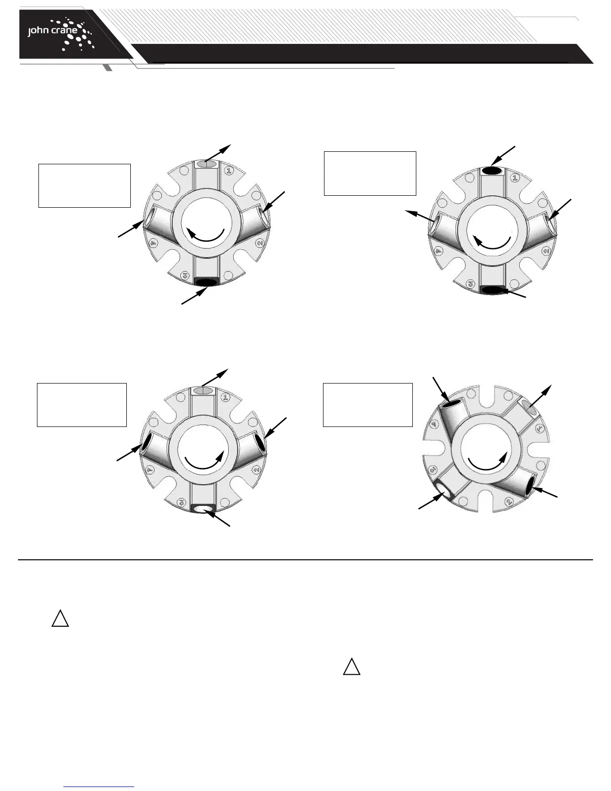
Clockwise
Rotation
Outlet
Port #1 - Outlet
Port #2 - Plugged
Port #3 - Inlet
Port #4 - Plugged
Inlet “I”
Clockwise
Rotation
Drain (Plugged)
Port #1 - Outlet/Vent
Port #2 - Inlet
Port #3 - Plugged
Port #4 - Plugged
Inlet “I”
Installing the Seal (continued)
The piping should follow the guidelines established in the John Crane Manual LE-Plan 52/53-A. It is also recommended that a Plan 11 (by-pass from
discharge) be used with the standard plan 52/53. For DIN pumps rotate gland 135˚ CCW. Use port #3 as inlet and #4 as outlet. Plug 1 and 2.
Preferred
Plugged
Plugged
Outlet “O”
Direction of view is from
the driver end of pump.
Port #1 - Vent
Port #2 - Inlet
Port #3 - Plugged
Port #4 - Outlet
45º Clockwise
Option #1
Outlet “O”
Vent (Plugged)
Option #1 requires
manual venting of
entrapped air through
port #1 prior to start-up.
Drain (Plugged)
For Counter Clockwise Shaft Rotation:
The piping should follow the guidelines established in John Crane Manual LE-Plan 52/53-A. It is also recommended that a Plan 11 (by-pass from discharge)
be used with the plan 52/53. For DIN style bolting pattern, rotate gland 45˚ clockwise.
Inlet
Counter
Clockwise
Rotation
Plugged
Outlet
Port #1 - Outlet
Port #2 - Plugged
Port #3 - Inlet
Port #4 - Plugged
Plugged
Inlet
Plugged
Counter
Clockwise
Rotation
TYPE 5620/5620P
DUAL O-RING CARTRIDGE SEAL
Installation, Operation & Maintenance Instructions
PAGE
5