15. Stand sleeve on its base and slide seal assembly over sleeve until seal
faces touch.
16. Install lubricated O-ring into ID groove of sleeve adapter or pumping ring.
17. Slide sleeve adapter over sleeve, aligning pins of adapter with pins of
sleeve. Push down to engage “drive flats” until adapter stops at step
of sleeve.
18. Carefully slide snap ring over the end of sleeve. Using assembly tool,
push the snap ring in place inside the sleeve adapter until it snaps in
place. Be careful not to scratch the sleeve adapter.
19. Install lubricated O-ring into OD groove of outboard mating ring.
20. Slide mating ring over sleeve, align pins and press in place.
21. Install lubricated O-ring into OD groove of outboard retainer.
22. Place spring inside retainer.
23. Insert drive ring in retainer with tabs facing opposite of spring. Align
notches with dents in retainer.
24. Insert anti X-ring in retainer.
25. Install lubricated O-ring on the primary ring. Push down until seated on
the step of the OD of primary ring.
26. Align notches on primary ring tail with drive ring tabs and press into bore
of retainer. Make sure primary ring is engaged into tabs and moves freely.
27. Place gland plate onto table with O-ring side up.
28. Insert seal assembly in gland plate, align pins and press in place. Turn
gland plate over and confirm that retainer is flush with end of gland plate.
29. Clean faces of primary and mating rings with denatured alcohol and a
lint-free cloth.
30. Insert O-ring in face groove of gland plate.
31. Making sure seal face does not fall out, slide gland plate over sleeve
until seal faces touch.
32. Carefully rotate gland plate until holes in sleeve are lined up with the
collar set screws.
33. Carefully press down on gland plate and install snap ring over the end
of sleeve. Do not over compress gland plate or this may damage
the seal.
34. Tighten set screws until they start to enter the sleeve ID.
35. Uniformly tighten cap screws on spacers.
36. Install gasket and sleeve O-ring.
37. Pressure test according to John Crane standard QA-5-0569.
38. Plug gland pipe taps as noted with metal plugs provided.
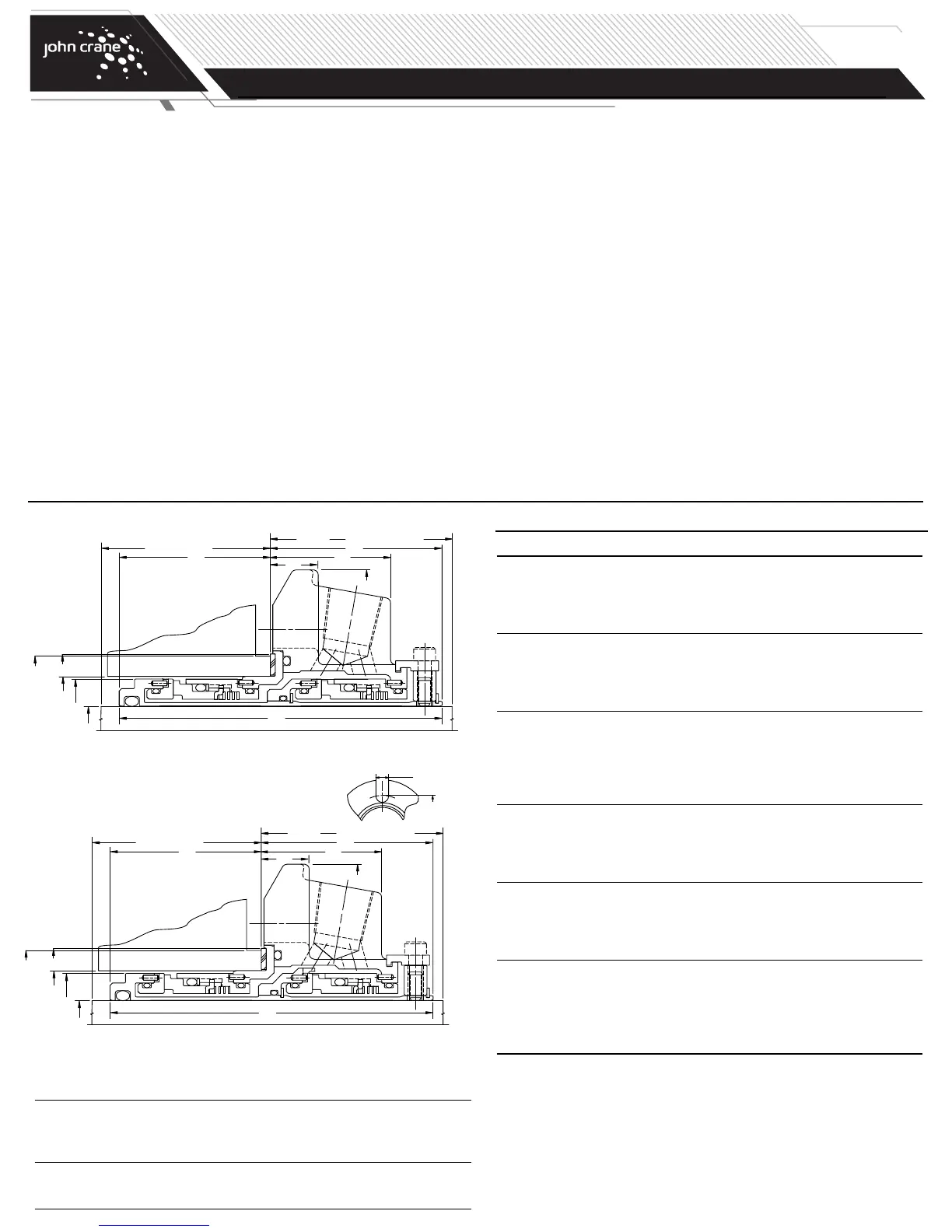
Type 5620 Installation Dimensions
Type 5620P Installation Dimensions
1.000 1.564 1.625 1.889 4.000 3.705 1.353 1.954 0.531 2.000 1.876 1.751 0.525 2.805
1.125 1.689 1.750 2.015 4.125 3.851 1.446 2.062 0.531 2.125 1.914 1.789 0.525 2.933
1
.250 1.812 1.875 2.294 4.250 3.851 1.446 2.062 0.531 2.125 1.914 1.789 0.525 3.213
1.375 1.939 2.000 2.421 4.375 3.851 1.446 2.062 0.531 2.125 1.914 1.789 0.525 3.338
1.500 2.187 2.250 2.680 4.875 3.995 1.487 2.125 0.593 2.187 1.995 1.870 0.525 3.599
1.625 2.312 2.375 2.812 5.000 3.995 1.487 2.125 0.593 2.187 1.995 1.870 0.562 3.766
1.750 2.406 2.480 2.918 5.250 3.995 1.487 2.125 0.593 2.187 1.995 1.870 0.563 3.875
1.875 2.549 2.625 2.918 5.250 3.995 1.487 2.125 0.593 2.187 1.995 1.870 0.563 3.875
2.000 2.673 2.750 3.015 5.500 4.355 1.601 2.312 1.063 2.375 2.167 2.042 0.562 4.000
2.125 2.798 2.875 3.360 5.859 4.355 1.601 2.313 0.593 2.375 2.167 2.042 0.687 4.469
2.250 2.923 3.000 3.485 6.500 4.355 1.601 2.312 0.593 2.375 2.167 2.042 0.687 4.566
2.375 3.048 3.125 3.610 6.500 4.545 1.717 2.466 0.625 2.825 2.204 2.079 0.687 4.719
2.500 3.301 3.375 3.891 6.750 4.545 1.717 2.563 0.625 2.625 2.107 1.982 0.687 5.000
2.625 3.551 3.625 4.062 6.750 4.594 1.625 2.500 0.625 2.562 2.219 2.094 0.687 5.170
2.750 3.551 3.625 4.062 6.750 4.594 1.625 2.500 0.625 2.562 2.219 2.094 0.687 5.170
2.875 3.614 3.750 4.186 7.000 4.594 1.725 2.500 0.625 2.562 2.219 2.094 0.687 5.312
3.000 3.864 4.000 4.469 7.750 4.594 1.787 2.562 0.685 2.625 2.157 2.032 0.812 5.720
3.125 4.022 4.125 4.600 7.875 4.687 1.593 2.562 N/A 2.687 2.250 2.125 0.812 5.845
3.250 4.022 4.134 4.600 7.437 4.687 1.593 2.510 N/A 2.635 2.302 2.177 0.812 5.845
3.375 4.246 4.375 4.850 8.125 4.687 1.593 2.562 N/A 2.687 2.250 2.125 0.812 6.095
3.500 4.371 4.500 4.975 8.250 4.687 1.593 2.562 N/A 2.687 2.250 2.125 0.812 6.220
3.625 4.500 4.625 5.100 8.375 4.687 1.593 2.562 N/A 2.687 2.250 2.125 0.687 6.250
3.750 4.625 4.724 5.199 8.750 4.687 1.593 2.562 N/A 2.687 2.250 2.125 0.687 6.770
3.875 4.750 4.875 5.375 8.750 4.687 1.593 2.562 N/A 2.687 2.250 2.125 0.812 6.636
4.000 4.875 5.000 5.500 9.000 4.687 1.593 2.562 N/A 2.687 2.250 2.125 0.812 6.761
4.125 5.000 5.125 5.625 9.000 4.687 1.593 2.562 N/A 2.687 2.250 2.125 0.812 6.886
4.250 5.125 5.250 5.750 9.250 4.687 1.593 2.562 N/A 2.687 2.250 2.125 0.812 7.011
4.500 5.375 5.500 6.000 9.500 4.687 1.593 2.562 N/A 2.687 2.250 2.125 0.812 7.261
4.750 5.625 5.750 6.313 10.375 4.687 1.593 2.562 N/A 2.687 2.250 2.125 0.812 7.574
5.000 6.125 6.760 7.260 12.000 5.515 1.749 3.043 N/A 3.168 2.598 2.473 0.812 10.000
5.250 6.375 7.010 7.510 12.250 5.515 1.749 3.043 N/A 3.168 2.598 2.473 0.812 10.250
5.500 6.625 7.500 8.000 12.687 5.515 1.749 3.043 N/A 3.168 2.598 2.473 0.937 10.500
L39L91 MIN. BOX DEPTH
L92
L90 MIN. NEAREST OBSTRUCTION
D3
L56
D26
D4
D1 +.000"
-.002"
D30
*
MIN.
TURN
DIAM.
L12
L23
L39L91 MIN. BOX DEPTH
L92
L90 MIN. NEAREST OBSTRUCTION
D3
L56
D26
D4
D1 +.000"
-.002"
D30
*MIN.
TURN
DIAM.
L12
L23
Type 5620/5620P Dual Cartridge Dimensional Data (inches)
Seal D4
Size/D1 D3 Min. Max. D26 L12 L23 L39 L56 L90 L91 L92 M N
Type 5620 Dual O-Ring Cartridge Seal Assembly (cont.)
*Oversize bore seals only
*Oversize bore seals only
Type 5620/5620P Oversize Bore Dual Cartridge
Dimensional Data (inches)
Seal D4 Min.
Size/D1 D3 Min. Max. D26 L12 L23 L39 L56 L90 L91 L92 M N Turn Diam.
1.375 1.939 2.875 3.023 5.375 3.851 1.446 2.062 0.625 2.125 1.914 1.789 0.562 4.062 3.268
1.750 2.406 3.500 3.925 6.500 3.995 1.487 2.125 0.656 2.187 1.995 1.870 0.687 5.093 3.885
1.875 2.549 3.625 3.734 6.500 3.995 1.487 2.125 0.656 2.187 1.995 1.870 0.687 5.093 4.006
2.125 2.798 3.875 4.250 7.250 4.355 1.570 2.282 0.749 2.407 2.198 2.073 0.687 5.687 4.264
2.500 3.301 4.750 5.078 8.000 4.545 1.788 2.563 0.749 2.625 2.107 1.982 0.687 6.062 5.000
2.625 3.551 4.625 4.740 8.000 4.594 1.788 2.500 0.749 2.562 2.219 2.094 0.687 6.062 5.000
2.750 3.551 4.750 4.875 8.000 4.594 1.697 2.407 0.656 2.532 2.312 2.187 0.687 6.062 5.139
TYPE 5620/5620P
DUAL O-RING CARTRIDGE SEAL
Installation, Operation & Maintenance Instructions
PAGE
3
 Loading...