XM Wheeled Dry Chemical Fire Extinguisher
Operation and Maintenance Manual
(Part No. S-50651)
2023-AUG-30 REV. 02 PAGE 15
MAINTENANCE
MAINTENANCE (Continued)
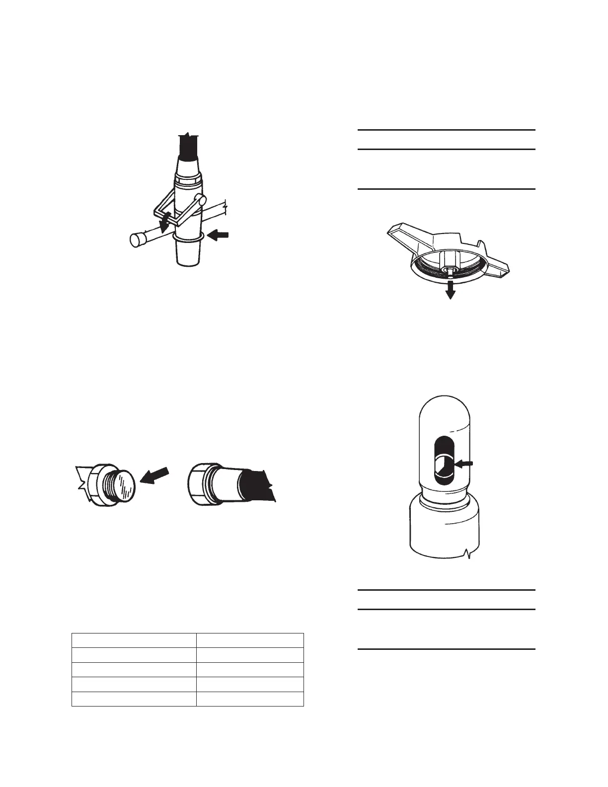
14. Check that the nozzle handle is forward in the closed position.
FIGURE 27
002654
15. Pull the ring pin and close the red tank valve.
16. Pull the ring pin and close the black dry chemical valve.
17. Pull the ring pin and open the green vent valve.
18. Open and close the cylinder valve using the hand wheel.
19. Pull the ring pin and open the blue hose clean-out valve.
20. Hold the nozzle rmly and open it. Escaping gas conrms that
the line is unobstructed and the nozzle valve is operable.
21. Remove the dry chemical agent hose at the adaptor, below
the tee and adjacent to black dry chemical valve.
22. Remove and discard the ruptured visual hose inspection disc
from the face of adaptor.
FIGURE 28
002678
23. Install the new visual hose inspection disc, Part No. 14236 for
Model 150-C, and Part No. 14237 for Model 350-C.
24. Return the hose to the adaptor and wrench tighten. Inspect
all the hose lines. Check for cuts, abrasions or weather-
checking.
25. Return the dry chemical tank valve handles to the operating
position:
Table 5: Valve operating positions
Valve Handle Operating Position
Red Tank Valve
Open
Green Vent Valve
Closed
Blue Hose Clean-out Valve
Closed
Black Dry Chemical Valve
Open
26. Insert the ring pins through the handles into the brackets and
seal with visual inspection seals (Part No. 5940).
27. Secure the dry chemical tank ll cap and hand tighten. Check
the gasket is in place before reinstalling the ll cap.
NOTICE
If the fill cap is an indicator model, be
sure the red indicator stem is in the
down position before securing fill cap.
FIGURE 29
002649
28. Re-read the nitrogen cylinder gauge, note pressure, check
ambient temperature, and see the Temperature Correction
Chart section of the ANSUL® Wheeled and Stationary Dry
Chemical Fire Extinguishers Operation, Inspection, Service
and Maintenance, and Recharge Manual (Part No. 79012).
Replace the cylinder if below minimum pressure.
FIGURE 30
002667
NOTICE
If the cylinder requires replacement, refer to
Recharge Section, steps 11 through 21 on
pages 7 through 11.
 Loading...