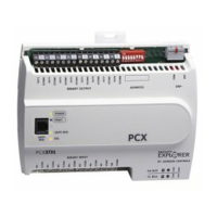
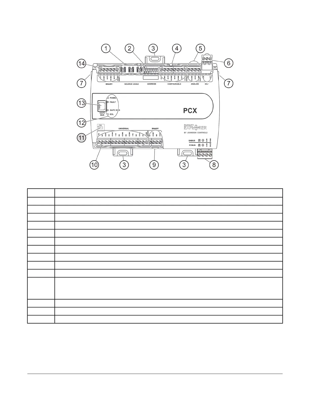
Figure 3: FX-PCX47 Physical Features
Table 1: FX-PCX47 Physical Features Callouts and Descriptions
Physical Feature DescriptionCallout
Binary Output (BO) Source Power Selection Jumper Pin Blocks, 3 – BO Jumper Pin Blocks. (See Table 3)
1
Device Address DIP Switch Block. (See Setting the Device Addresses)
2
Mounting Clip (One of Three)3
Configurable Output (CO) Terminal Blocks, 4 – Configurable Outputs. (See Table 3)
4
Analog Output (AO) Terminal Block, 2 – Analog Outputs. (See Table 3)
5
24 VAC, Class 2 Supply Power Terminal Block. (See Table 5)
6
Cover Lift Tab (One of Two). (See Removing the Controller Cover)
7
Sensor/Actuator (SA) Bus or Field Controller (FC) Bus Terminal Block. (See Table 5)
8
Binary Input (BI) Terminal Block, 2 – Binary Inputs. (See Table 3)
9
Universal Input (UI) Terminal Blocks, 6 – Universal Inputs. (See Table 3)
10
End-of-Line (EOL) Switch. (See Setting the End-of-Line (EOL) Switch)
Note: The EOL Switch is located under the controller cover. You must remove the cover to change the EOL switch
position.
11
LED Status Indicators. (See Table 8)
12
Sensor Actuator (SA) Bus or Field Controller (FC) Bus Port (RJ-12 6-pin Modular Jack). (See SA/FC Bus Port)
13
BO Terminal Block, 3 – Binary Outputs. (See Table 3)
14
3FX-PCX47 Expansion Input/Output Module Installation Instructions
 Loading...