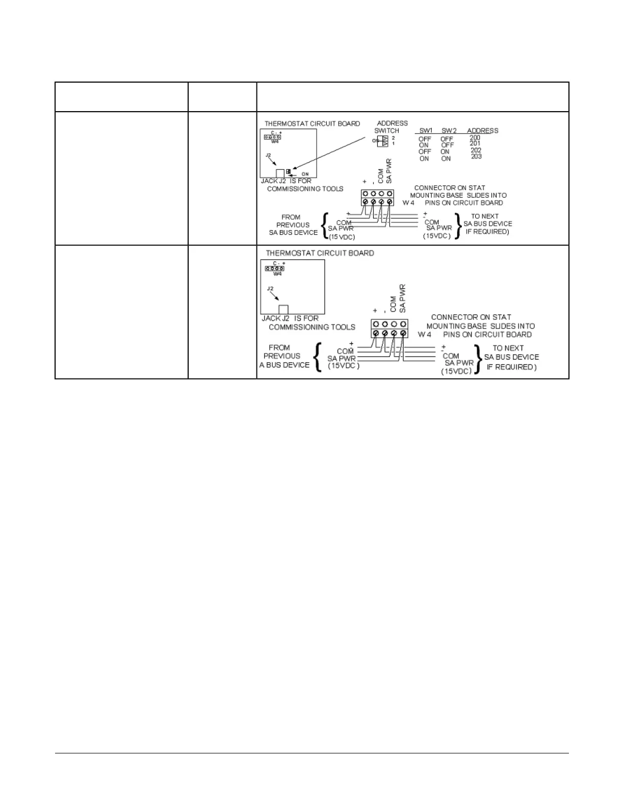
Table 2: Termination Details
Termination DiagramsType of
Input/Output
Type of Field Device
SA BusNetwork Stat with Terminals
Addressable
SA BusNetwork Stat with Terminals
(Fixed Address = 199)
Terminal Wiring Guidelines,
Functions, Ratings, and
Requirements
Input and Output Wiring Guidelines
Table 3 provides information and guidelines about the
functions, ratings, and requirements for the controller
input and output terminals; and references guidelines for
determining proper wire sizes and cable lengths.
In addition to the wiring guidelines in Table 3, observe
these guidelines when wiring controller inputs and
outputs:
• Run all low-voltage wiring and cables separate from
high-voltage wiring.
• All input and output cables, regardless of wire size or
number of wires, should consist of stranded, insulated,
and twisted copper wires.
• Shielded cable is not required for input or output
cables.
• Shielded cable is recommended for input and output
cables that are exposed to high electromagnetic or
radio frequency noise.
• Inputs/outputs with cables less than 30 m (100 ft)
typically do not require an offset in the software setup.
Cable runs over 30 m (100 ft) may require an offset
in the input/output software setup.
11FX-PCX47 Expansion Input/Output Module Installation Instructions
 Loading...