Hx-68P3 Series Outside Humidity and Temperature Transmitters Installation
Instructions
1
Refer to the QuickLIT website for the most up-to-date version of this document.
Application Requirements
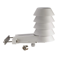
The Hx-68P3 Series Outside Humidity and
Temperature Transmitter measures and transmits
outside relative humidity (RH) from 0 to 100% and
temperatures from -40 to 140
F (-40 to 60C). In
addition to RH, the transmitter offers selectable
parameters including dew point, wet bulb temperature,
and enthalpy.
The integral weather shield provides ventilation, blocks
direct and reflected solar radiation, and blocks
precipitation without affecting performance. Mount the
transmitter outside on a pole or on a side of a building.
North American Emissions Compliance
United States
Canada
IMPORTANT: The Hx-68P3 Series Outside
Humidity and Temperature Transmitter is intended
to provide an input to equipment under normal
operating conditions. Where failure or malfunction of
the humidity and temperature transmitter could lead
to personal injury or property damage to the
controlled equipment or other property, additional
precautions must be designed into the control
system. Incorporate and maintain other devices,
such as supervisory or alarm systems or safety or
limit controls, intended to warn of or protect against
failure or malfunction of the humidity and
temperature transmitter.
IMPORTANT: Le Hx-68P3 Series Outside Humidity
and Temperature Transmitter est destiné à
transmettre des données entrantes à un équipement
dans des conditions normales de fonctionnement.
Lorsqu'une défaillance ou un dysfonctionnement du
humidity and temperature transmitter risque de
provoquer des blessures ou d'endommager
l'équipement contrôlé ou un autre équipement, la
conception du système de contrôle doit intégrer des
dispositifs de protection supplémentaires. Veiller
dans ce cas à intégrer de façon permanente
d'autres dispositifs, tels que des systèmes de
supervision ou d'alarme, ou des dispositifs de
sécurité ou de limitation, ayant une fonction
d'avertissement ou de protection en cas de
défaillance ou de dysfonctionnement du humidity
and temperature transmitter.
This equipment has been tested and found to
comply with the limits for a Class A digital device
pursuant to Part 15 of the FCC Rules. These limits
are designed to provide reasonable protection
against harmful interference when this equipment is
operated in a commercial environment. This
equipment generates, uses, and can radiate radio
frequency energy and, if not installed and used in
accordance with the instruction manual, may cause
harmful interference to radio communications.
Operation of this equipment in a residential area
may cause harmful interference, in which case users
will be required to correct the interference at their
own expense.
This Class (A) digital apparatus meets all the
requirements of the Canadian Interference-Causing
Equipment Regulations.
Cet appareil numérique de la Classe (A) respecte
toutes les exigences du Règlement sur le matériel
brouilleur du Canada.
Hx-68P3 Series Outside Humidity and Temperature
Transmitters
Installation Instructions
HE-68P3-0N000, HT-68P3-0N000
Part No. 24-9647-10, Rev. B
Issued March 2016