42 Johnson Controls, Inc. SLC Wiring Manual — P/N 51870:G 04/23/2009
Control Modules Wiring a NAC with Addressable Control Modules
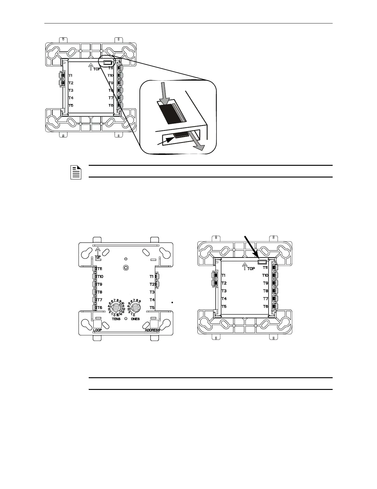
Figure 7.2 M300CJ Top and Rear View - Jumper Location
7.2.1 Wiring a Solenoid with the M300CJ-REL
Figure 7.3 shows the connections to wire the M300CJ-REL to a solenoid.
Figure 7.3 M300CJ-REL Wiring Connections and Rear View - Jumper Location
NOTE: The M300CJ-REL will not function on an SLC loop that is programmed for CLIP mode.
FCMBackJump.wmf, FCMBackJumpcl.wmf
Jumper J1 must be removed when using the M300CJ
on an FFT-7 or FFT-7S telephone circuit (see the
Voice Alarm System Manual, FireVoice 25/50 Manual
or DVC Manual as appropriate for your equipment) and
when supervising 24VDC NAC power using the
no-relay alternative wiring (see Appendix A.2.3, “Using
the Addressable Control Module Without Relay”).
J1
Rear View
To remove J1 from the:
1. Insert a small prying tool, such
as a screwdriver or probe,
behind J1.
2. Using the tip of the prying tool,
slide J1 toward the rear of the so
that it exits from the slot in the
back.
Prying tool
NOTE: When using IFC-3030/IFC2-3030 and the Control type ID, do not remove jumper J1.
J1
SLC (-)
SLC (+)
24 VDC (-)
24 VDC (+)
Solenoid A (-)
Solenoid A (+)
Solenoid B/A (+)
Solenoid B/A (-)
M300CJ-REL
Wiring Connections
When using the
M300CJ-REL for Class B
applications, remove jumper
J1.
M300CJ-REL
Rear View - Jumper Location