Connecting the power source
To terminate the power connection to the device,
complete the following steps:
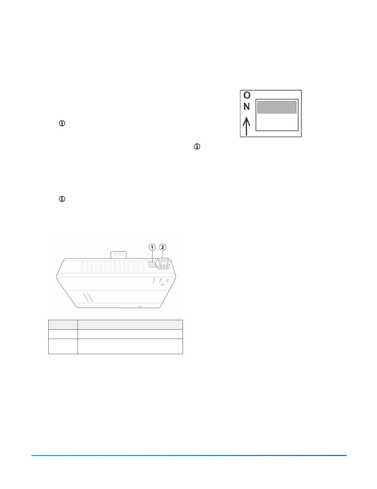
1. Connect power to the device according to the
power source you use:
- If you use a 24 VAC power transformer, connect
the 24 VAC supply power wires from the
transformer to the removable power terminal
block plug on the device, see callout 2 in
Figure 5. The connections are HOT and COM
(common). Insert the plug.
Note: Power supply wire colors can
be different on transformers not
manufactured by Johnson Controls.
Follow the transformer manufacturer’s
instructions and the project installation
drawings.
- If you use the 24 VDC power adapter, plug the
power adapter into the round 24 VDC barrel
plug located in the upper right corner of the
device. See callout 1 in Figure 5. Connect the 24
VDC power adapter to 120 VAC.
Note: Do not use both the power terminal
block and the power adapter. Select
either one.
Figure 5: Supply power wiring: 24 VAC transformer or
24 VDC adapter
Callout Description
1 Barrel plug for 24 VDC power adapter
2 Terminal block plug for 24 VAC power
transformer
2. Go to Setting end-of-line switches.
Setup and adjustment
The following sections describe the setup and adjustment
of the device.
Setting end-of-line switches
The network devices at each end of an FC bus segment
must be set as network terminated devices. The device
has one EOL switch for each of its FC bus connections that
sets the device as a network terminated device on the
bus.
To set a device as an FC bus terminated device, position
the switch on the EOL switch block to the ON position as
shown in the following figure.
Figure 6: FC bus EOL switch in the factory default ON
(up) position
Note: The device is shipped with each EOL switch
in the initial factory position, ON as shown in Figure
6. If the device is not a terminated device on the FC
bus, reposition the switch on the EOL switch block to
the Off (down) position.
Set the EOL switches appropriately for FC Bus-1. The
device follows the same rules as other switch-terminating
devices listed in the Setting Terminations section of the MS/
TP Communications Bus Technical Bulletin (LIT-12011034).
For the RS-485 connection, set the EOL termination to ON,
or install an EOL terminator, for the two devices located at
either end of each bus segment on an RS-485 bus. Set the
EOL switch to off, or do not install an EOL terminator, for
all other devices on the bus segment on an RS-485 bus.
Powering on the device
Apply power to the device. After you apply power, the
device requires approximately three minutes to start
up and become operational. See LED test sequence at
startup.
Startup is complete and the device is operational when
the heartbeat LED flashes purple and the fault LED is off.
The various LEDs are shown in LED status indicators.
Disconnecting power from the device
Disconnect power from the device by removing the
terminal block plug from the power terminal port on the
device, as shown in Figure 5, or disconnecting the power
adapter cable.
When you disconnect or lose supply power from the
device, the device becomes nonoperational when the
power management settings expire. The heartbeat LED,
as shown in Figure 7, remains on (blue), and the super
capacitor powers the device for approximately 30 seconds
in order to back up volatile data in nonvolatile memory.
The heartbeat LED goes off when the data backup is
complete.
JC-RTR11002-0 BACnet Router Installation Guide 5
 Loading...