JCI-6724 • 05/24/04 — Page 3 of 4
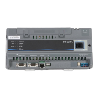
The Face Plate
WIRING DIAGRAMS
The following wiring diagrams are provided:
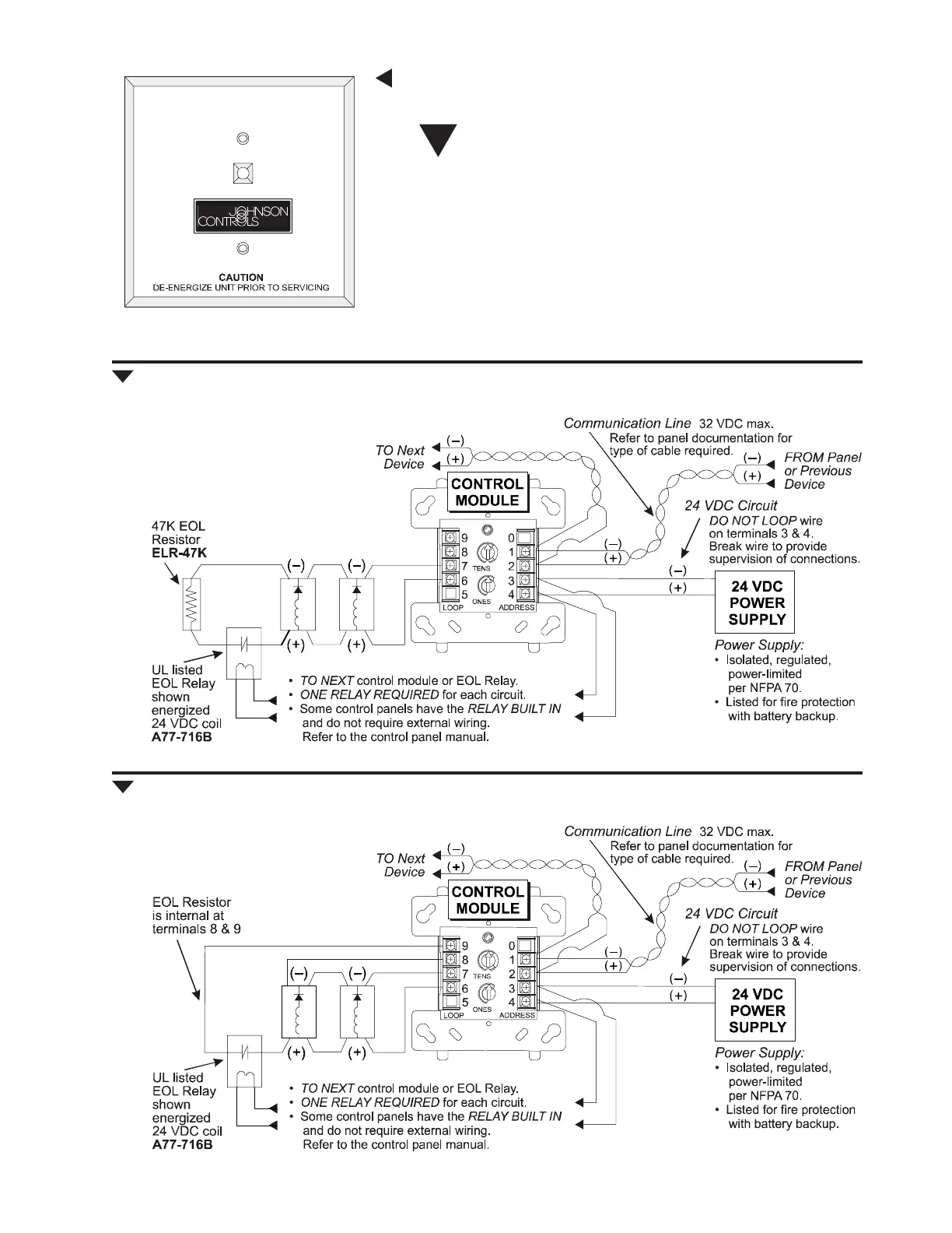
1) M300CJ: Typical notification appliance circuit configuration,
NFPA Style Y.
2) M300CJ: Typical fault-tolerant notification appliance circuit con-
figuration, NFPA Style Z.
3) M300CJ: Typical wiring for speaker supervision and switch-
ing, NFPA Style Y.
4) M300CJ: Typical fault-tolerant wiring for speaker supervision
and switching, NFPA Style Z.
5) M300RJ: Relay module wiring diagram.
Fig. 1 M300CJ: Typical notification appliance circuit configuration, NFPA Style Y.
Fig. 2 M300CJ: Typical fault-tolerant notification appliance circuit configuration, NFPA Style Z.
• Connect modules to Listed compatible Johnson Controls control panels only.
• All wiring shown is supervised and power limited.
• Module polarities are shown in alarm.
• Connect modules to Listed compatible Johnson Controls control panels only.
• All wiring shown is supervised and power limited.
• Module polarities are shown in alarm.
6827wir1.wmf
6827wir2.wmf
j6724fc.wmf, JCI01rev.tif