Materials and special tools needed
• Small, straight-blade (1/8 in. or 3.2mm) or Phillips #2
screwdriver for securing wires in the terminal blocks
• 8 mm (5/16 in.) wrench or 10 mm (3/8 in.) 12-point
socket to tighten the square coupler bolt
• Several shims or washers to mount the CVM/CVE
• Power screwdriver, 100 mm (4 in.) extension socket,
punch, drill, and 3.5 mm (9/64 in.) drill bits to mount
the controller
• Pliers to open and close the damper
• Required length of 3.97 mm (5/32 in.) ID pneumatic
tubing and barbed fittings
Physical features
The following figures display the physical features of
the CVM/CVE controllers, and the accompanying table
provides a description of the physical features and a
reference to further information where required.
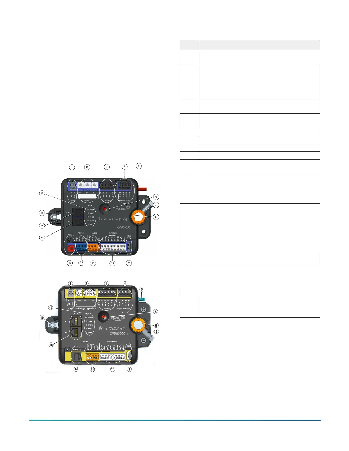
Figure 1: CVM03050 physical features
Figure 2: CVE03050 physical features
Table 1: CVx series physical features
Physical features: description and references
1 Supply Power Terminal Block: Gray terminals. See
Supply power terminal block.
2 Rotary Switches:
CVM: Decimal addressing. See Setting the device
address on CVM models.
CVE: Controller number. See Setting the controller
number for CVE models
3 Binary Output (BO) Terminal Block: Black terminals. See
Table 5.
4 Configurable Outputs (CO) Terminal Block: Black
terminals. See Table 5.
5 Dual Port Fitting.
6 Manual Override Button. See Mounting.
7 Coupler Bolt
8 Controller Coupler. See Mounting.
9 Universal Serial Bus (USB) 2.0 Host Type A Port
Note: The USB feature is not currently supported.
10 Universal Inputs (UI) Terminal Block: White terminals.
See Table 5.
11 Sensor Actuator (SA) Bus Terminal Block: Orange
terminal. See SA Bus terminal block.
12
(CVM
only)
Field Controller (FC) Bus Terminal Block: Blue terminal;
may also be used for N2 connections, see FC Bus
terminal block (or N2 protocol as required) on CVM
controllers.
13
(CVM
only)
EOL (End-of-Line) Switch. See Setting the End-of-Line
(EOL) switch (CVM models only).
14 Sensor (SA Bus) Port: RJ-12 6-Pin Modular Jack. See
Sensor (SA Bus) Port.
15
(CVM
only)
FC Bus Port: RJ-12 6-Pin Modular Jack. See FC Bus Port
on CVM models.
16 Captive Spacer and Screw.
17 LED Status Indicators. See LED Table.
18 Ethernet Ports: ETH-1 and ETH-2. See BACnet/IP
Ethernet Network Topology for CVE controllers
Mounting
Observe the following guidelines when mounting a CVM/
CVE controller:
• Ensure that the mounting surface can support the
controller and any user-supplied enclosure.
• Mount the controller on a hard, even surface whenever
possible.
• Use shims or washers to mount the controller securely
and evenly on the mounting surface.
• Mount the controller in an area free of corrosive vapors
that matches the ambient conditions specified in the
Technical specifications section.
M4-CV Series VAV Box Controllers Installation Guide2