the VAV box Balancing Tool, specified network sensors, or
other SA Bus devices with RJ-12 plugs.
When the FEC is configured for N2 communication, the SA
Bus port must be used to download and commission the
controller.
A DIS1710 Local Controller Display also can be connected
to the SA Bus port (but only on FEC models without
integral display and push-buttons).
The Sensor port is connected internally to the SA bus
terminal block. See Table 4 for more information. The
Sensor Port pin assignment is shown in Figure 6.
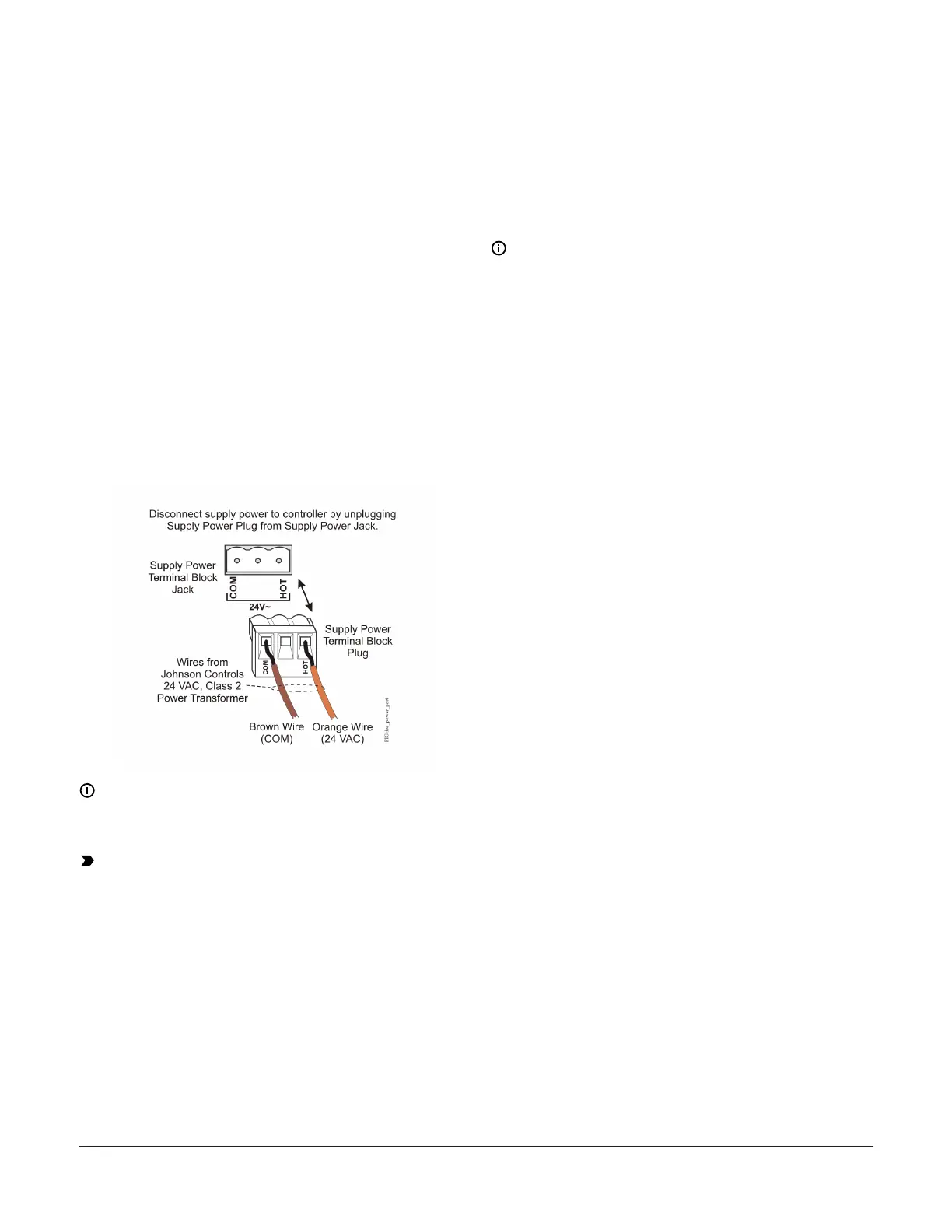
Supply power terminal block
The 24 VAC supply power terminal block is a gray,
removable, 3-terminal plug that fits into a board-mounted
jack on the top right of the controller.
Wire the 24 VAC supply power wires from the transformer
to the HOT and COM terminals on the terminal plug as
shown in Figure 7. The middle terminal on the supply
power terminal block is not used. See Table 4 for more
information about the Supply Terminal Block.
Figure 7: 24 VAC supply power terminal block wiring
Note: The supply power wire colors may be different
on transformers from other manufacturers. Refer to
the transformer manufacturer’s instructions and the
project installation drawings for wiring details.
Important: Connect 24 VAC supply power to
the controller and all other network devices so
that transformer phasing is uniform across the
network devices. Powering network devices with
uniform 24 VAC supply power phasing reduces
noise, interference, and ground loop problems.
The controller does not require an earth ground
connection.
Wireless Field Bus applications
When configured for BACnet MS/TP communication, the
controller can also be installed in a ZFR/ZFR Pro Wireless
Field Bus System.
To configure a controller for use with a Wireless Field Bus
system:
1. Wire the input/output terminals and SA bus.
Note: In wireless network applications, do not
connect any wires to the FC Bus terminal block.
(Connect the SA/FC terminal block on an Input/
Output Module (IOM) to an SA bus only.)
2. Connect the ZFR/ZFR Pro Wireless Field Bus Router to
the FC bus port (RJ-12 modular jack) on the front of
the controller.
3. Ensure that the controller's device address DIP
switches are set to the correct device address. See
Setting the device addresses.
4. Set DIP switch 128 to ON, which enables wireless
operation on the controller.
For more information on the ZFR Pro Wireless Field Bus
system, refer to the WNC1800/ZFR182x Pro Series Wireless
Field Bus System Product Bulletin (LIT-12012320).
For more information on the ZFR Wireless Field Bus sys-
tem, refer to the ZFR1800 Series Wireless Field Bus System
Product Bulletin (LIT-12011336).
Terminal Wiring Guidelines,
Functions, Ratings, and
Requirements
Input and Output wiring guidelines
Table 2 provides information and guidelines about the
functions, ratings, and requirements for the controller
input and output terminals; and references guidelines for
determining proper wire sizes and cable lengths.
In addition to the wiring guidelines in Table 2, observe
these guidelines when wiring controller inputs and
outputs:
• Run all low-voltage wiring and cables separate from
high-voltage wiring.
• All input and output cables, regardless of wire size or
number of wires, should consist of stranded, insulated,
and twisted copper wires.
• Shielded cable is not required for input or output
cables.
• Shielded cable is recommended for input and output
cables that are exposed to high electromagnetic or
radio frequency noise.
• Inputs/outputs with cables less than 30 m (100 ft)
typically do not require an offset in the software setup.
Cable runs over 30 m (100 ft) may require an offset in
the input/output software setup.
Metasys System FEC1611 and FEC1621 Field Equipment Controller Installation Guide 5

 Loading...


