Metasys Integrator® MIG3500 Series Installation Instructions 3
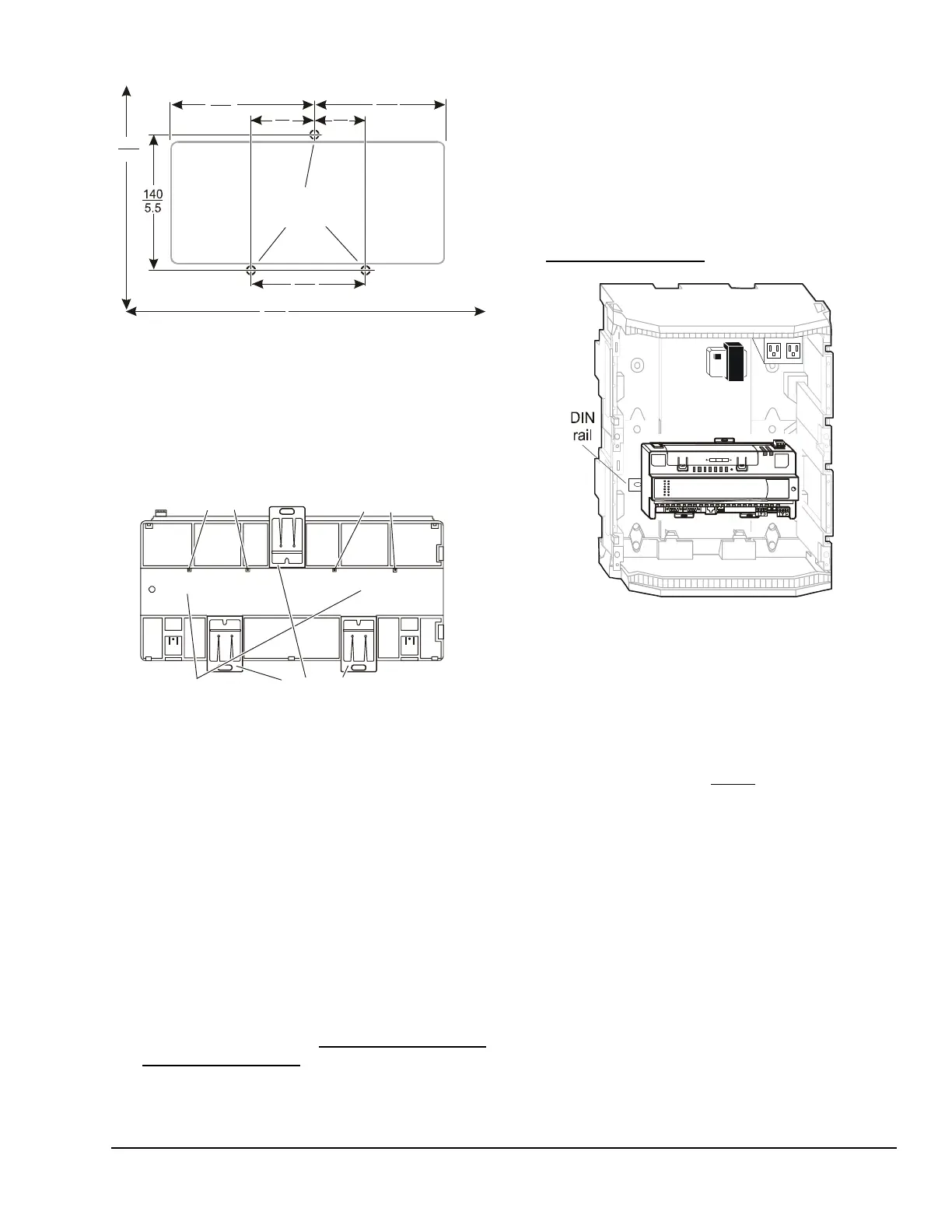
2. Ensure that the bottom two mounting clips are
pulled outward and snapped firmly into the
extended position (Figure 3).
3. Hang the MIG3500 by the DIN rail hooks (Figure 3)
on the top track of the DIN rail, and position the
MIG3500 DIN rail channel snugly against the
tracks of the DIN rail.
4. Push the bottom mounting clips up to secure the
MIG3500 on the DIN rail tracks.
To remove the MIG3500 from the DIN rail, snap the
bottom DIN clips to the outward extended position, and
carefully lift the MIG3500 off the DIN rail.
Enclosure Mount Applications
Mount the enclosure per the manufacturer’s
instructions and mount the MIG3500 in the enclosure
following the guidelines in the Location Considerations
and Mounting the MIG3500
sections.
Legacy MIG300 Replacement Considerations
Follow these important guidelines if the MIG3500
replaces an existing MIG300 controller:
• The unit size of the MIG3500 is slightly longer than
the MIG300; however, the MIG3500, like the
MIG300, is designed for DIN-rail mounting on the
horizontal plane (Figure 4). You can also mount it
with screws, either horizontally or vertically. See
Mounting the MIG3500
for details.
• The wire termination locations on the MIG3500 are
different from the MIG300 (Figure 1). Pay close
attention to this when routing wires to their new
locations on the MIG3500.
• Similar to the MIG300, the MIG3500 also requires
24 VAC power. See the Wiring
section.
• The N2 Bus termination on the MIG300 is labeled
N2 Port, whereas the N2 Bus termination on the
MIG3500 is called N2 - RS485. If using N2 Bus
wiring that includes a shield, refer to the
N2 Communications Bus Technical Bulletin
(LIT-636018) for additional information on
terminating a shield.
• For the MIG3500, an Ethernet port is available and
is used only for downloading firmware. For details,
refer to the Metasys Integrator 3500 Series
Commissioning Guide (LIT-12011439).
Figure 2: MIG3500 Mounting Screw Hole
Dimensions and Mounting Area Requirements,
mm (in.)
FIG:MIGmnthol
121
4.8
Mounting
Holes
66
2.6
140
5.5
55
2.2
130
5.1
210
8.3
350
13.8
Mounting
Holes
Figure 3: DIN Rail and Mounting Clip Features
on the Back of an MIG3500
FIG:MIG_bck
DIN Rail
Channel
Mounting Clips
(in Extended Positions)
DIN Rail
Hooks
DIN Rail
Hooks
Figure 4: Recommended Installation Location of
MIG3500 and Transformer in Standard Enclosure
FIG:MIGewc_cmp
 Loading...