Metasys Integrator® MIG3500 Series Installation Instructions 7
Setup and Adjustments
Battery
The MIG3500 is shipped with a battery installed and
connected. If the MIG3500 experiences a power loss,
the battery maintains the current time and date stored
in the unit. The battery is non-rechargeable and field
replaceable.
Turning On the MIG3500
After applying 24 VAC power, the MIG3500 requires
approximately 2 minutes to start up and become
operational. See the LED Test Sequence at Startup
section.
Startup is complete and the MIG3500 is operational
when the (green) RUN LED is On steady and the (red)
FAULT LED is Off (Figure 11). If this is a new MIG3500
without a firmware image, the RUN LED continues to
flash, indicating that the unit needs to be
commissioned with the MUU. Refer to the Metasys
Integrator 3500 Series Commissioning Guide
(LIT-12011439) for additional information on
commissioning an MIG3500.
Disconnecting Power from the MIG3500
When 24 VAC supply power to a MIG3500 is
disconnected or lost, the MIG3500 turns off
immediately.
Setting N2 Bus End-of-Line Switch
N2 Bus applications require at least one terminated
device on each N2 Bus segment; but two terminated
devices, one at each end of the N2 Bus segment, are
recommended. The MIG3500 has an End-of-Line
(EOL) switch that allows you to set the MIG3500 as a
terminated device. The MIG3500 is shipped with the
EOL A switch in the factory default, ON (up) position
(Figure 9). Set the EOL A switch to the appropriate
position for each MIG3500 in your network. For more
details, refer to the Setting Terminations section of the
N2 Communications Bus Technical Bulletin
(LIT-636018).
Setting RS485 EOL B Switch
RS485 serial protocol bus segments require proper
EOL termination to reduce interference from signal
bounce back on the bus segment. An EOL switch for
the Vendor A - RS485 port on the MIG3500 is provided
for this purpose. Vendor devices at either end of the
RS485 bus must be set as terminated devices. The
MIG3500 is shipped with the EOL B switch in the
factory default, ON (up) position (Figure 10). Set the
EOL B switch to the appropriate position for each
MIG3500 in your network.
Troubleshooting
LED Status Indicators
The MIG3500 has a bank of LEDs to indicate power
and network communication status. Figure 11 shows
the LEDs and Table 3 describes the LED indications.
IMPORTANT: Wait for the MIG3500 to complete
the start-up sequence and the RUN LED to go On
steady before initiating any other action on the
MIG3500.
Figure 9: N2 Bus EOL A Switch in the
Factory Default ON (Up) Position
FIG:MIG_EOL
1
Figure 10: RS485 EOL B Switch in the Factory
Default ON (Up) Position
FIG:MIG_EOL
1
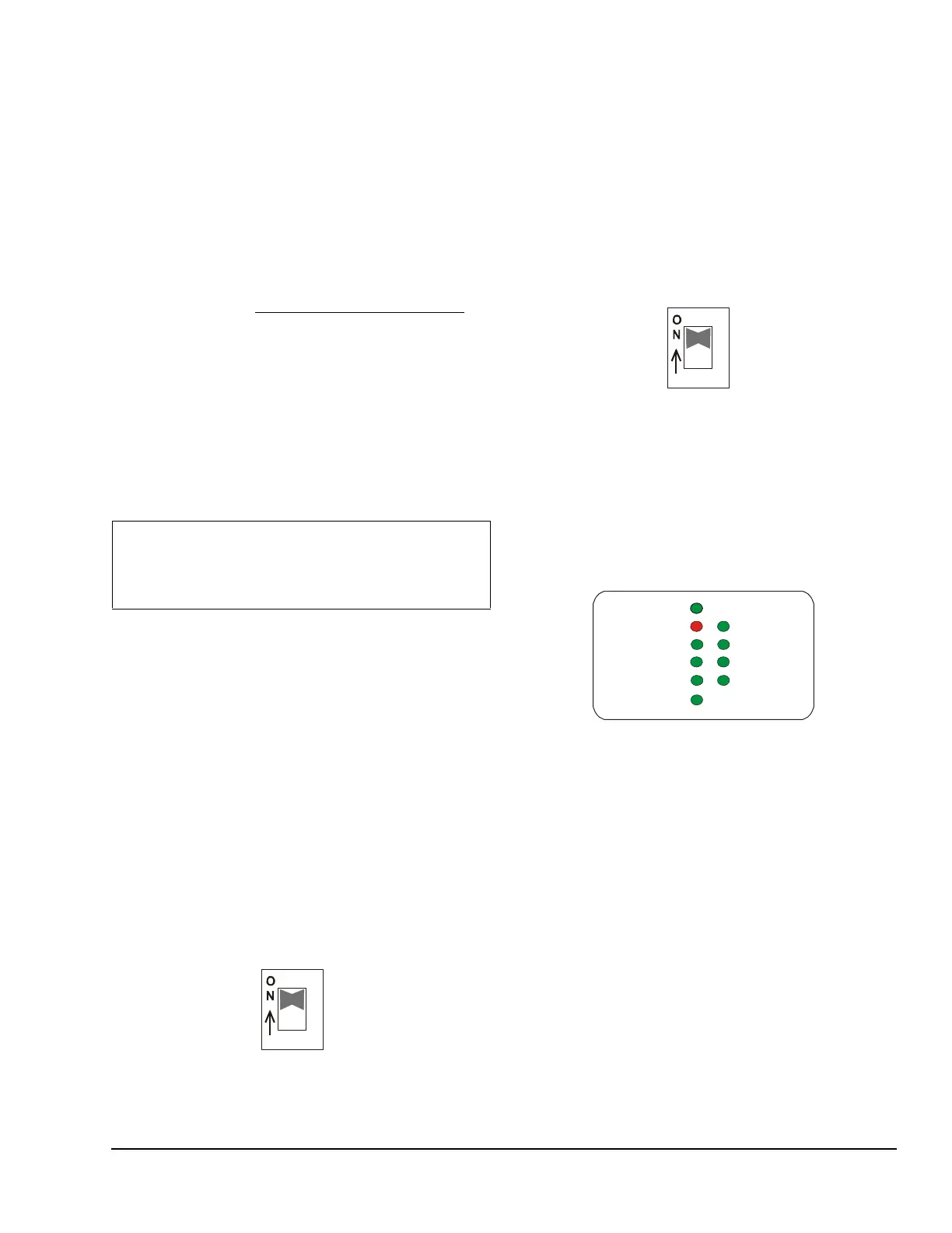
Figure 11: MIG3500 LED Designations
ETHERNET
10 LINK
100 LINK
RUN
POWER
FAULT
N2 PORT TX
VENDOR A TX
VENDOR B TX
VENDOR B RX
FIG:MIG_LED
 Loading...