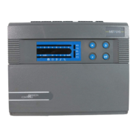
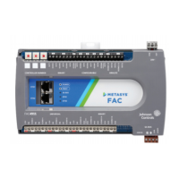
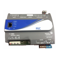
Table 11: Call-out table for Universal input and Binary input terminal blocks as viewed from the
bottom of an NCE25
Callout Description
1 Universal inputs can be defined as the following:
• Voltage Analog inputs (0 -10 VDC)
• Current Analog inputs (4-20 mA)
• Resistive Analog inputs (0-2k Ohm)
- RTD: 1k Nickel, 1k Platinum, or A99B SI
- NTC: 10k Type L or 2.225k Type 2
• Dry contact Binary inputs
2 Front of NCE.
3 Binary inputs can be defined as:
• Dry contact maintained
• Pulse counter mode (50 Hz at 50% Duty Cycle)
4 Back of NCE (Flush to Mounting Surface)
Terminal functions, ratings, requirements, and
wiring guidelines
Input and output wiring guidelines
Table 12 provides information and guidelines about the functions, ratings, and requirements for
the NCE input and output terminals and references to guidelines for determining proper wire sizes
and cable lengths.
In addition to the wiring guidelines in Table 12, observe these guidelines when wiring inputs and
outputs:
• Run all low-voltage wiring and cables separate from high-voltage wiring.
• Ensure all input and output cables, regardless of wire size or number of wires, consist of
stranded, insulated, and twisted copper wires.
• Shielded cable is not required for input or output cables.
• Shielded cable is recommended for input and output cables that are exposed to high
electromagnetic or radio frequency noise.
NCE25 Installation Instructions20

 Loading...


