24 Technical Bulletin—TC-9102
!
CAUTION: Connections to the on/off or 3-speed fan control
terminals may carry up to 250 VAC. Isolate live and
neutral supply lines (double-pole switch) before
servicing.
To reach the jumpers and switches, open the controller by gripping the
cover with thumb and finger on both sides above center and pull the
cover off using the lower edge as a hinge. Replace the cover by resting
the lower edge of the cover against the base and then pressing the cover
firmly to engage all four retaining lugs.
If the controller is connected to a communications bus, a network address
must be set. Refer to the project documentation for the address setting for
the controller. Addresses 0 to 63 can be set on the address switches. The
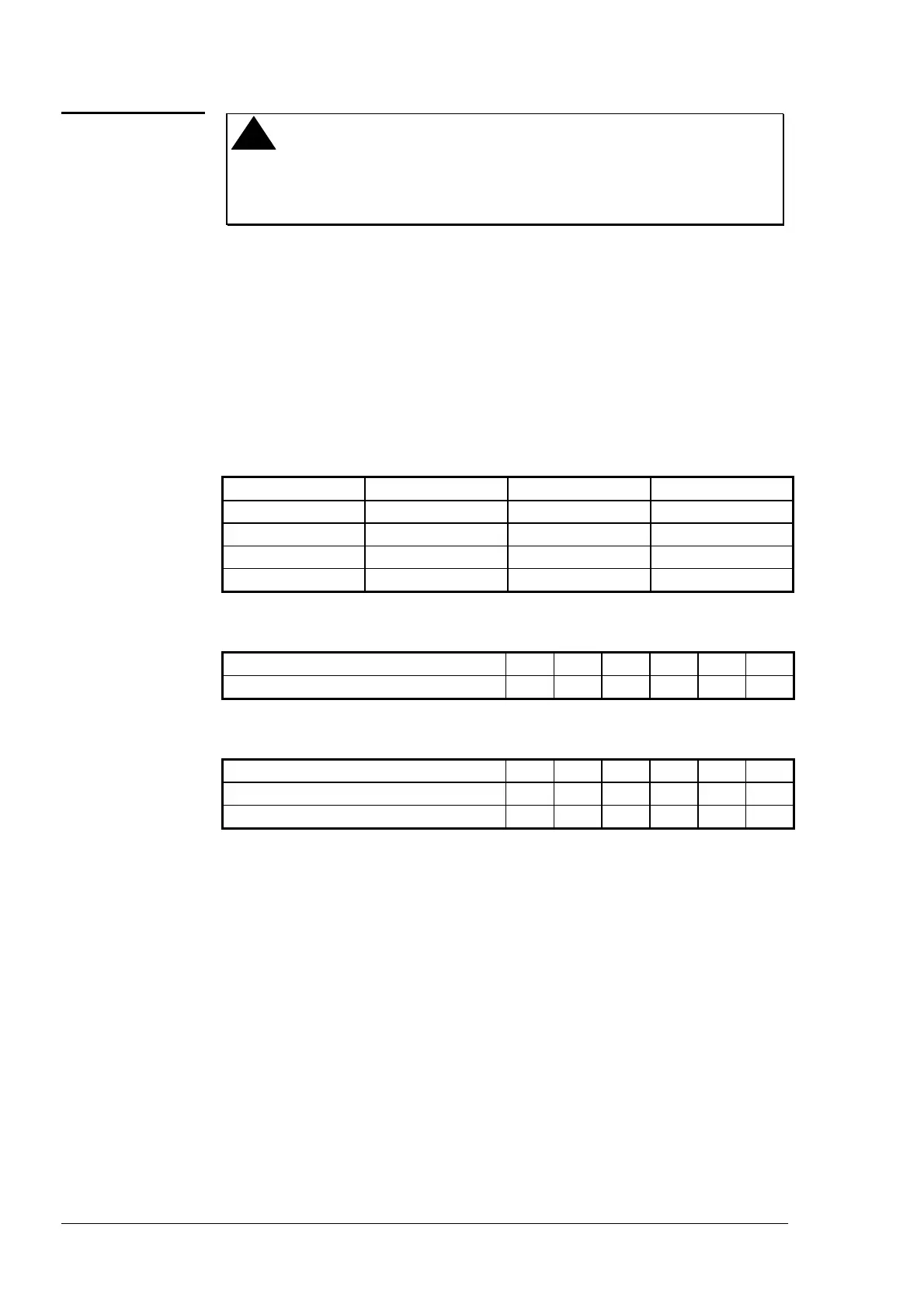
zone jumpers allow addressing up to 255 as follows:
Zone 1 Jumper Zone 2 Jumper Address Switch Network Address
OUT OUT 0 to 63 0 to 63
IN OUT 0 to 63 64 to 127
OUT IN 0 to 63 128 to 191
IN IN 0 to 63 192 to 255
The setting on the Address Switches is in binary format:
Switch Number: 1 2 3 4 5 6
Decimal Equivalent: 1 2 4 8 16 32
Example (Address 43):
Switch Number: 1 2 3 4 5 6
Switch Position: ON ON OFF ON OFF ON
Decimal Equivalent: 43 = 1 + 2 + 0 + 8 + 0 + 32
Remove the
Gain Jumper JP2 (RED)
to reduce the proportional band to
half of the factory setting (gain x 2). (Factory setting is 2K.)
When the
Integral Time Jumper JP2 (BLUE)
is not installed (as
delivered by the factory), the integral action of the controller is disabled.
Insert the jumper to obtain the factory set default value of four minutes
(0.25 repeats per minute).
Set Jumpers
JP3
as shown in Figure 20, depending on whether a
TM-9180 with LCD Display (lower position) or a TM-9150/9160/9170
(upper position) is connected.
Jumper and
Switch
Selections
Address
Switches and
Zone Jumpers
Jumpers
 Loading...