MR4PMUHV Electronic Temperature/Defrost Control with Relay Pack Product/Technical Bulletin 5
Wiring
WARNING: Risk of Electric Shock.
To avoid electric shock or damage to equipment,
disconnect all power supplies before wiring any
connections. More than one disconnect may be
necessary to completely de-energize equipment.
Wiring Sensors and Binary Input
Wire the sensors and binary input (if used) as shown
in Figures 8-9. The Sensor (S1 or S2) and Sensor
Common (SC) wires are interchangeable when
using the A99B temperature sensors. The binary
input shares a common terminal with the sensors.
SC
S1S2D
V1
V1
V2
V2
Internal to Control
Evaporator
Temperature
Sensor
Binary
Input
(Switch)
Main
Temperature
Sensor
Sensor
Common
12 VAC
O1
O1
O2
O2
Note: Black boxes indicate unused terminals.
B
L
K
W
H
T
R
E
D
G
R
N
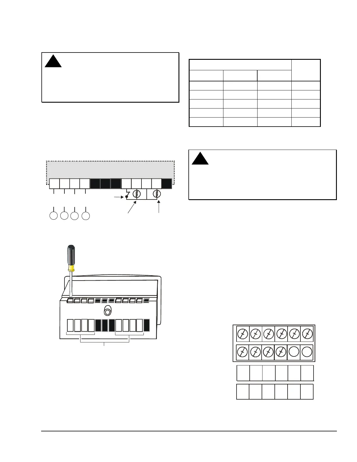
Figure 8: Wiring the Control Module
Loosen screw to open terminal;
tighten screw to secure wiring.
Insert wiring here.
V1
V1
V2
V2
O1
O1
O2
O2
D
D
S2
S2
SC
SC
S1
S1
Note: Black boxes indicate unused terminals.
Figure 9: Rear View of the Control Module
Use Temperature Sensor Offset to compensate for
sensor leads longer than 300 ft (if F is used) or
165 m (if C is used). See Table 1 and Temperature
Management Functions: Temperature Sensor Offset.
Table 1: Sensor Wire Size and Length
Wiring the Relay Pack
WARNING: Risk of Electric Shock.
To avoid electric shock or damage to equipment,
disconnect all power supplies before wiring any
connections. More than one disconnect may be
necessary to completely de-energize equipment.
See Figure 10 for arrangement of terminals on the
terminal block in the relay pack. See Figures 11-12 for
sample wiring diagrams.
Follow these wiring guidelines:
Ensure all wiring conforms to the National Electric
Code and local regulations.
Use 14 AWG copper wire for motor loads up to 12 FLA
and noninductive loads up to 15 A.
Use 12 AWG copper wire with an insulation rating of
75°C (minimum) for motor loads up to 16 FLA and
noninductive loads up to 20 A.
Use wire no longer than 50 ft (15 m).
Ensure all circuits have a common disconnect and are
connected to the same pole of the disconnect.
L2
FNO
120
240
DH1
DH2
FNC
CP1 CP2
ALM
(Not
used)
(Not
used)
Relay
Pack
Terminal
Block
Terminal
Labels
on
Circuit
Board
Figure 10: Relay Pack Terminal Block
 Loading...