Terminal Wiring Guidelines,
Functions, Ratings, and
Requirements
Input and Output Wiring Guidelines
Table 4 provides information and guidelines about the
functions, ratings, and requirements for the controller
input and output terminals; it also references guidelines
for determining proper wire sizes and cable lengths.
In addition to the wiring guidelines in Table 4, observe
these guidelines when wiring controller inputs and
outputs:
• Run all low-voltage wiring and cables separate from
high-voltage wiring.
• All input and output cables, regardless of wire size or
number of wires, should consist of stranded, insulated,
and twisted copper wires.
• Shielded cable is not required for input or output
cables.
• Shielded cable is recommended for input and output
cables that are exposed to high electromagnetic or
radio frequency noise.
• Inputs/outputs with cables less than 30 m (100 ft)
typically do not require an offset in the software setup.
Cable runs over 30 m (100 ft) may require an offset
in the input/output software setup.
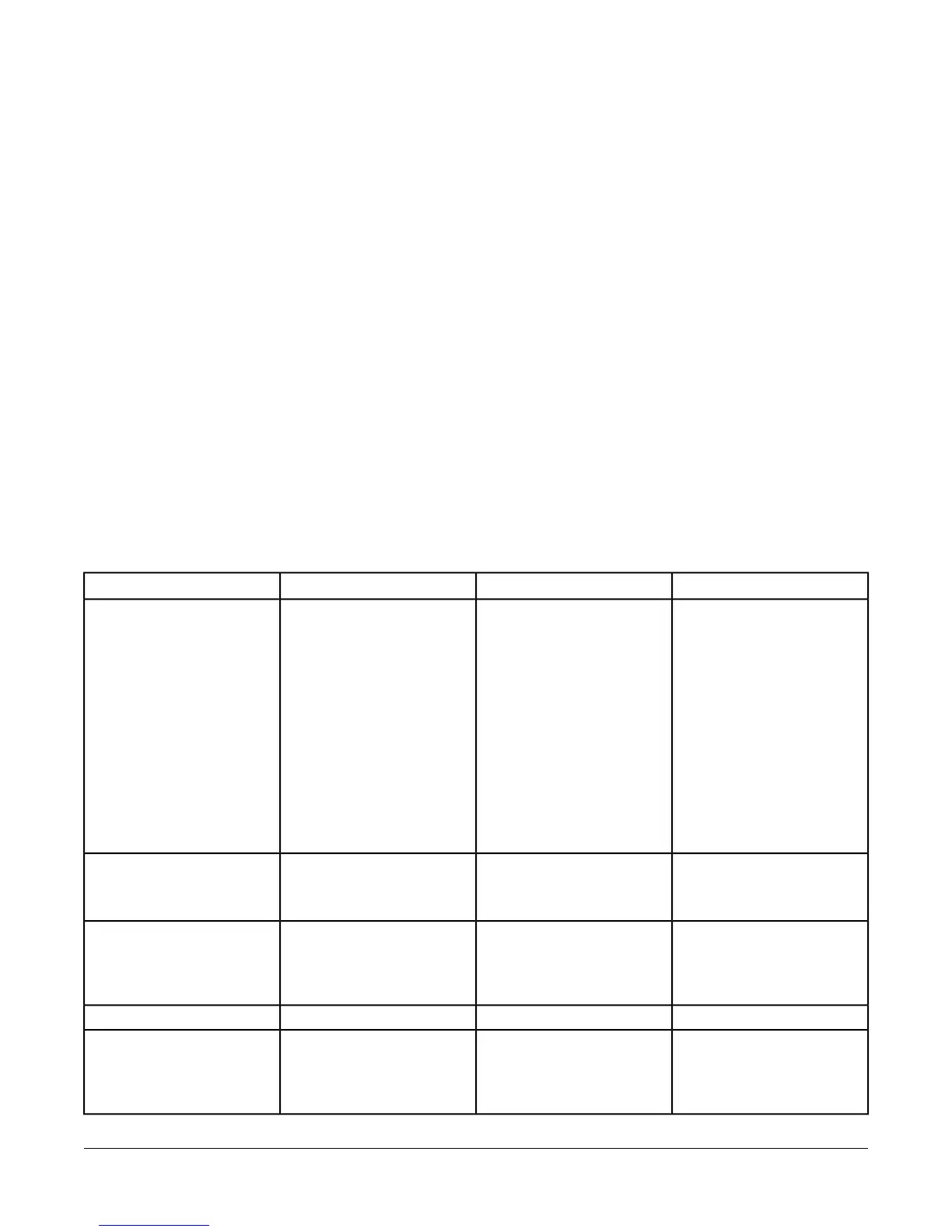
FEC26 Series Point Type Counts per Model
The following table shows the different point types and counts available in the FEC2511 and FEC26 and Series
controllers.
Table 3: FEC26 Series Point Type Counts per Model
FEC26(Asia Only model)Signals AcceptedPoint Types
64 (Does not support Current
Mode)
Analog Input, Voltage Mode,
0–10 VDC
Analog Input, Current Mode,
4–20 mA
Analog Input, Resistive Mode,
0–2k ohm, resistance
temperature detector (RTD) (1k
NI [Johnson Controls], 1k PT,
A99B SI), negative temperature
coefficient (NTC) (10k Type L,
2.252k Type 2)
Binary Input, Dry Contact
Maintained Mode
Universal Input (UI)
26Dry Contact Maintained Mode
Pulse Counter/Accumulator
Mode (High Speed), 100 Hz
Binary Input (BI)
22Analog Output, Voltage Mode,
0–10 VDC
Analog Output, Current Mode,
4–20 mA
Analog Output (AO)
32 (Ext Power only)24 VAC TriacBinary Output (BO)
42Analog Output, Voltage Mode,
0–10 VDC
Binary Output Mode, 24 VAC
Triac
Configurable Output (CO)
13FEC26 Field Equipment Controllers Installation Instructions

 Loading...


