Important: Do not connect an external power source
to a BO when the BO power source jumper
is in the internal power (INT) position.
Connecting external power to a BO that
sources internal power can damage the
controller and void any warranties.
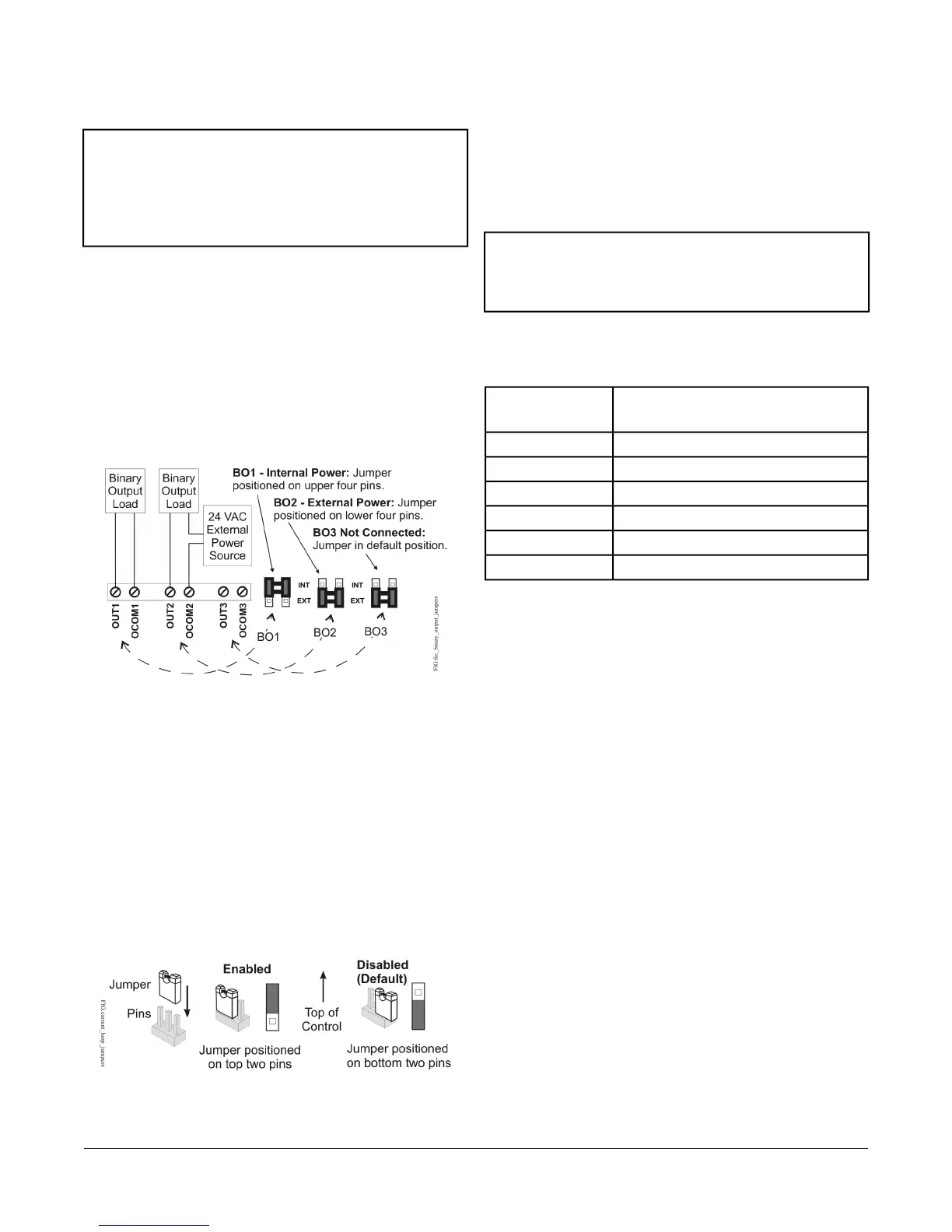
The BO source power selection jumpers determine
whether a BO provides internal power (sourced from the
controller) to the output load (INT position) or requires
an external power source (EXT position) for the output
load. Figure 12 shows an example of a controller BOs
and the associated power selection jumpers to the right
of the BOs terminal block.
Figure 12: Example Binary Outputs and the
Associated Source Power Jumper Positions
Universal Input Current Loop Jumpers
The Universal Input (UI) current loop fail-safe jumpers
are on the circuit board under the controller cover near
the UI terminals (Figure 10). When a UI is defined (in the
system software) as a 4-20 mA Analog Input and the UI’s
current loop jumper is in the Disabled (default) position
(Figure 13), the 4-20 mA current loop circuit opens
whenever power to the controller is interrupted or off.
Figure 13: Current Loop Jumper Positions
Setting the current loop jumper to the Enabled position
(Figure 13) connects an internal 100 ohm resistor across
the UI terminals, which maintains the 4-20 mA current
loop circuit even when power to the controller is
interrupted or off.
Important: Current Loop jumpers must be in the
Disabled (default) position for all UIs that
are not set up to operate as 4-20 mA analog
inputs.
Table 8 identifies the current loop jumpers associated
with each UI on the FEC26 controller.
Table 8: FEC26 UI Inputs and Jumper Labels
Jumper Label on Circuit BoardUniversal Input
Label
J20IN1
J21IN2
J22IN3
J23IN4
J24IN5
J25IN6
Setting Up an Integral or Local
Display
FEC2621 models have an integral LCD and push button
user interface that allows you to set up and monitor the
FEC, the FEC I/O points, and the modules and I/O points
connected on the SA bus. FEC2611 models do not have
an integral display, but can be connected to a DIS1710
Local Controller Display. For detailed information on
setting up and operating either an integral user interface
or a remotely connected DIS1710 display, refer to the
DIS1710 Local Controller Display Technical Bulletin
(LIT-12011270).
Commissioning Field Controllers
You commission field controllers with the Controller
Configuration Tool (CCT) software, via a Bluetooth®
Wireless Commissioning Converter, a USB dongle with
ZigBee®, Ethernet connection, or in BACnet router mode
when connected to an NAE or NCE. Refer to the
Controller Tool Help (LIT-12011147) for detailed
information on commissioning controllers.
23FEC26 Field Equipment Controllers Installation Instructions

 Loading...


