Table 6: NCM LED Designations, Normal Status, and Descriptions
Descriptions/Other ConditionsNormal StatusLED Designation
On Steady = Unit is getting power from either the battery or 24 VAC
power.
Off Steady = Unit is shut down.
On SteadyPOWER (Green)
Blink = Data is transferring on the Ethernet connection. Ethernet traffic
is general traffic (may not be for the NCM).
Off Steady = No Ethernet traffic, probably indicates a dead Ethernet
network or bad Ethernet connection.
BlinkETHERNET (Green)
On Steady = Ethernet connection is established at 10 Mbps.On Steady10/LINK (Green)
On Steady = Ethernet connection is established at 100 Mbps.On Steady100/LINK (Green)
Blink = Normal communications; the N2/LON Bus is transmitting and
receiving data. Blinks are generally in sync with data transmission,
but should not be used to indicate specific transmission times.
Off Steady = No field controllers are defined to N2/LON Bus in the
NCM.
BlinkFC BUS (Green) or LON BUS
(Green)
None. PEER COM is On only during startup.Off SteadyPEER COM (Green)
On Steady = NCM software is fully initialized.
On 1 second, Off 1 second = NCM software is starting up, or
controller is waiting to be commissioned and/or requires a data
download.
On 0.5 seconds, Off 0.5 seconds = NCM software is shutting down.
On SteadyRUN (Green)
On Steady = Battery defective. Blink = Data Protection Battery is not
installed. Memory cannot be backed up. Connect or install battery.
Off SteadyBATT FAULT (Red)
On Momentarily, then Off = Internal fault has occurred.Off SteadyFAULT (Red)
Repair Information
If you replace an NCM on a site with a new NCM for any
reason or add a new NCM to a site, you must update the
system database to ensure that the new NCM is
recognized and able to communicate with the site.
Refer to the NCM45x0-2 Network Control Module
Commissioning Guide (LIT-12011176) for information on
removing an NCM from service and configuring a
replacement NCM.
Note: Batteries removed from this device must be
recycled or disposed of in accordance with local,
national, and regional regulations. Only certified
technicians or qualified building maintenance
personnel should service Johnson Controls
products.
Table 7: NCM45x0-2 Ordering Information
DescriptionProduct Code Number
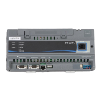
Requires a 24 VAC power supply. Each model includes two RS-232-C serial
ports, one USB serial port (unused), one Ethernet port, and an MS-BAT1020-0
Data Protection Battery.
MS-NCM45x0-2 (Base features of each
NCM45x0)
Supports one N2 trunk (RS-485 port). Up to 100 devices (60 to 200 TC-9100s)
are supported on the N2 trunk when a repeater is used.
MS-NCM4510-2
Includes a LONWORKS port and supports one LONWORKS trunk. Up to 127 devices
are supported on the LONWORKS port.
MS-NCM4520-2
Buy American equivalent to MS-NCM4510-2MS-NCM4510-2G
Buy American equivalent to MS-NCM4520-2MS-NCM4520-2G
Repair for MS-NCM4510-2MS-NCM4510-702
Repair for MS-NCM4520-2MS-NCM4520-702
9NCM45x0-2 Series Network Control Module Installation Instructions