Figure 4: FC Bus terminal block and wiring connections
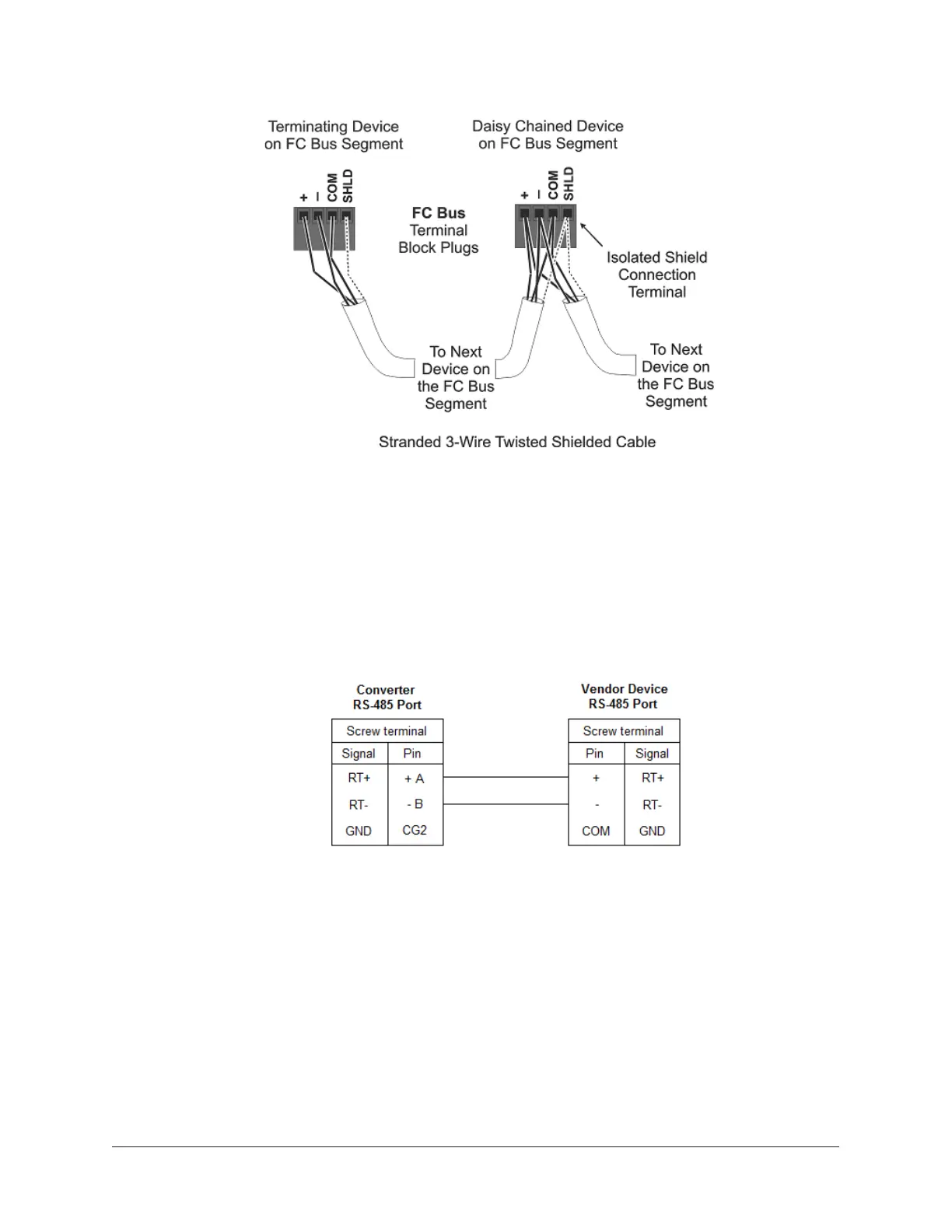
3. Wire from the RS-485 terminal on the converter to the RS-485 port on the vendor device (Figure
5). The RS-485 bus is a two-wire network.
a. Connect the converter's + A terminal to the device's + (or A) terminal.
b. Connect the converter's - B terminal to the device's - (or B) terminal.
c. If the device has a Signal Ground or Reference terminal,connect this to the converter's
CG2 terminal.
Figure 5: Connection between converter and device
4. To add additional vendor devices, wire from one device to the next as shown in Figure
6. No more than two wires may be connected to each terminal to ensure the daisy chain
configuration. See Wiring rules and guidelines for network integrations for the Modbus
protocol.
9NAE35/NAE45 Installation Guide