Vertical Wallbox-Mounted or Surface-Mounted Occupancy Sensing NS Series Network Sensors with LCD
Installation Instructions
4
10. Align the tabs on the bottom edge of the mounting base with the slots on the bottom edge of the network
sensor assembly and rotate the assembly onto its mounting base.
Note: On the model featuring a screw terminal block, be certain that the terminal block pins align with the holes in
the terminal block.
11. Use a 1/16 in. (1.5 mm) Allen wrench or Johnson Controls T-4000-119 Allen-Head Adjustment Tool to tighten
the security screw and fasten the network sensor assembly to the mounting base.
Note: Do not overtighten the security screw to avoid damaging the unit.
12. Before use, clean the lens of the PIR occupancy sensor with a soft, dry cloth.
Note: Do not use water or other solvents to clean the lens.
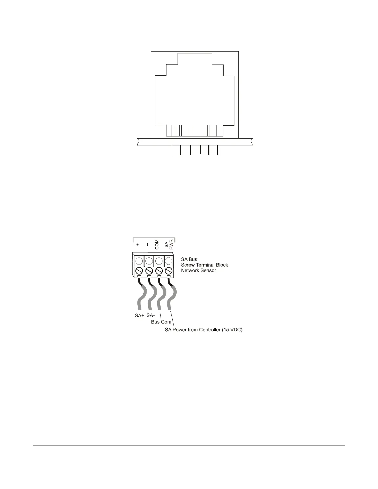
Figure 1: Modular Jack Pin Number Assignments
Pin Number Assignment for
Straight-Through Cable
Printed Circuit Board
SA Powe
r (Network
Sensor)
2
3
45
6
1
FIG:mdlr_jck
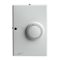
S
A
+
S
A
-
SA B
us
Com
mo
n
(Tool
A
cces
s)
S
A
P
ower
(T
oo
l
A
cc
ess
)
Main
Network
Port
S
A
Bus Co
m
m
o
n
(
Ne
t
work
Sensor)
Figure 2: Wiring to the Screw Terminal Block