VFD68 Variable Frequency Drives Product Bulletin 3
Operation Panel on 230 VAC and 460 VAC
Models
The RUN, MON, and PRM LEDs provide drive status
and indicate the type of information being displayed on
the operation panel (Figure 2).
RUN LED: The LED state (on steady, flashing, or
flickering) provides information regarding the drive and
motor run status.
MON LED: Indicates that the monitor is displaying the
drive’s run status. Press SET to scroll through run
frequency, output amperes, and output voltage.
PRM LED: Indicates that the monitor is set to display
parameters and parameter values and allows you to
view and edit parameter values.
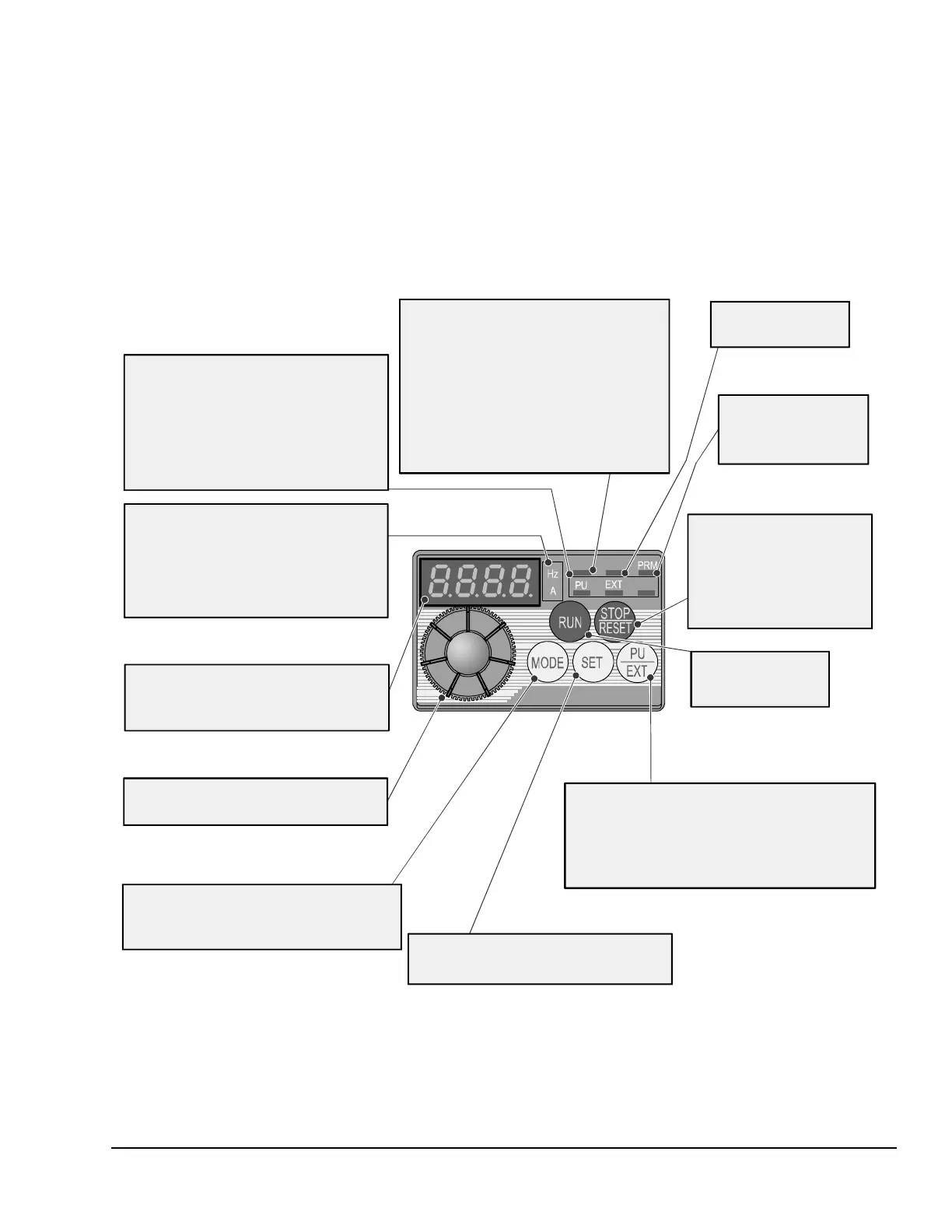
Figure 2: Operation Panel for 230 VAC and 460 VAC Models
RU N
MON
NET
Operation mode indication LEDs
PU:
EXT:
NET:
Lit to indicate PU manual operation
mode.
Lit to indicate External operation mode.
(Lit at power-ON at initial setting.)
Lit to indicate Network operation mode.
These turn OFF when the command source
is not on the operation panel.
Unit of measurement indication
Hz
A (
Hz A
(lit) indicates operating frequency
(motor speed) is displayed.
lit) indicates operating amperes is
displayed.
and are not lit when values other than
frequency or amperes are displayed.
Monitor (4-digit LED)
Shows the frequency, parameter number,
parameter values, motor speed during
operation, and error codes.
Setting dial
In PRM mode,
scroll the setup parameters
to view and change the parameter values.
Mode button
Used to change each setting mode.
Pressing changes the operation mode
between PRM mode and PU mode.
MODE
SET button
Used in PRM mode to select a parameter
and save a new parameter value.
Parameter setting mode
indication
PRM
lit to indicate
parameter setting mode.
Monitor indication
MON lit to indicate
monitoring mode.
STOP/RESET button
Press to stop
and motor.
the VFD68 drive
If the VFD68 drive
is stopped because of a fault
condition, press this button
to reset the drive and resume
Operation mode switchover
Switches between the PU mode and EXT mode.
When using the EXT mode (using an external device
connected to AI1 or AI2, such as a pressure
transducer or control analog output, with a
0–5 V, 0 10 V, or 4 20 mA output), press this key
to light the EXT indication.
––
Run button
Press to start the
VFD68 drive and motor.
RUN indicator LED
On Steady:
Slow flash:
Fast flash:
RUN lit or flickering during operation.
Motor running in forward rotation.
Motor running in reverse rotation.
The drive cannot run due to a
condition such as the SD and STF
inputs are not connected or when
the frequency command is less
than the starting frequency.
FIG:oprtn_pnl

 Loading...

